dS2824
dS2824 User Manual v4.12
So now the relay we wish to control is mapped to virtual relay 29 and the input that is going to
control it is mapped to input 161, which is the 2
nd
input on mapping 31. The input number was
obtained from the table on a previous page.
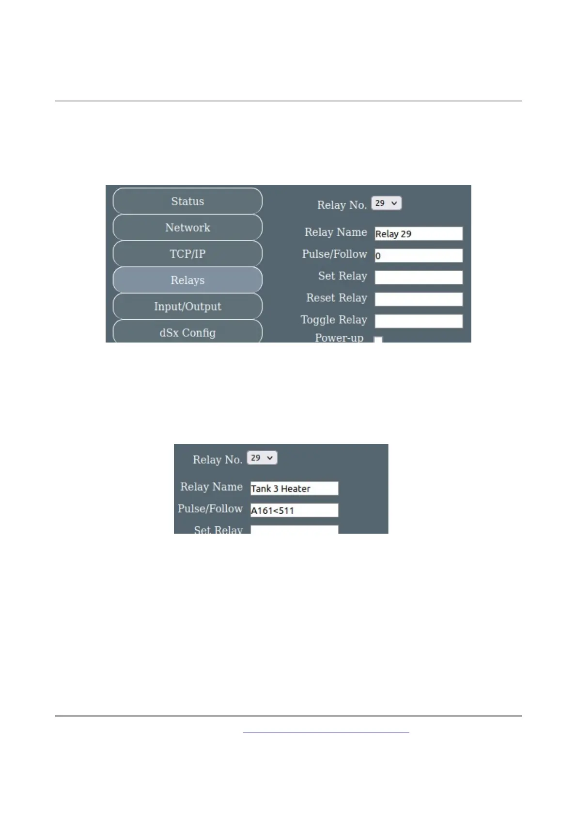
Now we can go to the Relays page and configure the relay. Select relay 29 from the drop-down
box.
If you want, you can give the relay a more descriptive name. To use input 161 as an analogue
input we use A161. If we wanted a digital input it would be D161. Enter the following into the
Pulse/Follow box:
A161<511
All other fields can remain empty.
Now the relay will turn on when the input is less that 511.
Although A161<511 is simple to understand, its not actually the best way to do it. Analogue
inputs by their nature can jitter around. This can cause the relay to pulse on/off as the input
jitters close to 511. A better way is to include some hysteresis like this:
(A161<509&!R29)|(A161<513&R29)
This means the relay will turn on when the input is below 509 (508 or less), but will not turn
off again until the input is above 512 (513 or more). The greater the difference between the
two numbers, the greater the hysteresis.
Copyright © 2016-2021, Devantech Ltd.
All rights reserved.
www.robot-electronics.co.uk
27