dS2824
dS2824 User Manual v4.12
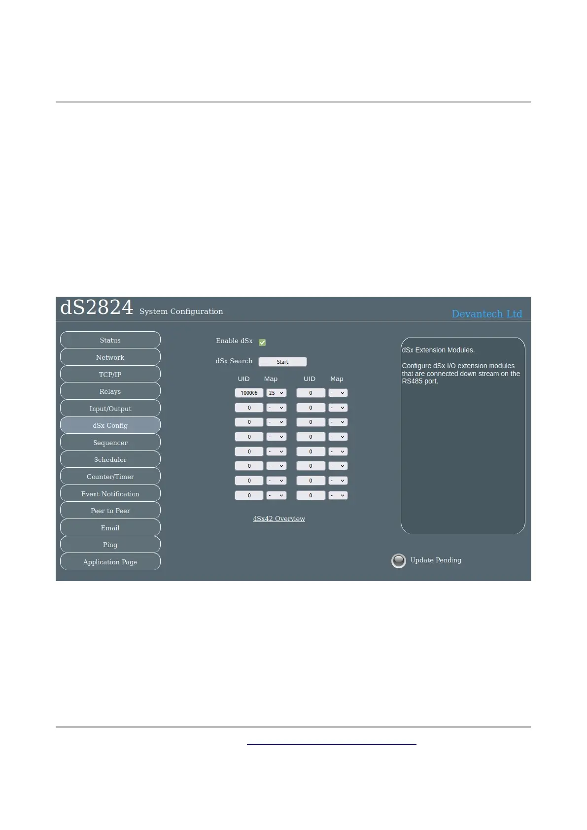
dSx Configuration
Used to configure dSx42 modules connected to the RS485 bus.
dSx42 modules are extension I/O modules that are connected to the RS485 bus (serial port 3).
Up to 16 dSx modules may be added, controlled by the dS2824 as if they are local I/O. The
outputs are mapped to 2 of the 32 relays – real or virtual and the inputs can be accessed in
the range 100-164. dSx modules are powered from the 12v output on the dS2824’s RS485
connector and wired using a separate pair in the cable. A 2 pair cable is therefore required.
The dSx modules use very little current (less than 7mA each) and 15 of them are easily pow-
ered at the far end of 100 meters of cheap cable. Maximum distance is 305 meters (1000 ft).
Configuration
dSx mode is enable by checking the Enable dSx box. This will configure serial port 3, the
RS485 port, to 250k baud as used by the dSx modules. If un-checked the port will be config-
ured to the Modbus settings on the TCP/IP page. Reset the board after checking or un-check-
ing this box.
To automatically search for dSx modules on the RS485 bus click the Start button. This will
clear all previous devices and mappings and fill the list with all devices found and offer a de-
fault mapping.
Copyright © 2016-2021, Devantech Ltd.
All rights reserved.
www.robot-electronics.co.uk
23