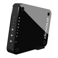
Introduction 14
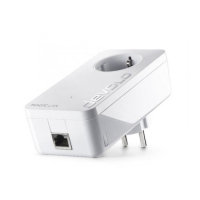
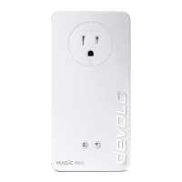
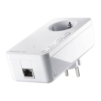
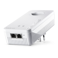
devolo Magic 1 WiFi
2-1
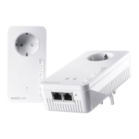
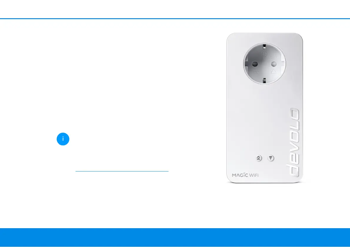
access point over the Powerline network (e.g.
Internet router).
b Its integrated electrical socket can be used
like a normal wall socket to supply power to an
additional network device or a power strip.
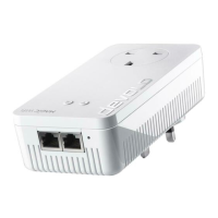
The devolo Magic 1 WiFi
2-1
features
b An integrated electrical socket,
b A PLC button with LED status display,
b A Wi-Fi button with LED status display,
b Four internal WiFi antennas,
b Two network connectors
b A reset button (next to the network connec-
tors).
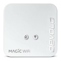
The LED status displays can be disabled. You
can find more information about this in
Chapter 4 Network configuration or in the
product manual for the devolo Cockpit soft-
ware available online at
www.devolo.global/devolo-cockpit.
Fig. 2: devolo Magic 1 WiFi
2-1
with country-specific
connector and power socket