17 Introduction
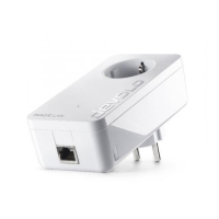
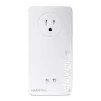
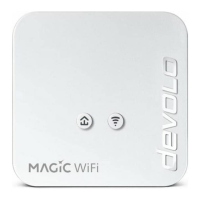
devolo Magic 1 WiFi
2-1
2.3.1Reading the PLC indicator light
The integrated PLC indicator light (LED) shows the
status for the devolo Magic 1 WiFi
2-1
by illumina-
ting and/or flashing:
LED Flashing be-
haviour
Meaning LED status display
(web interface*)
1 Red LED Lights up for
up to 2 sec.
Start-up process Cannot be disabled
2 Red LED Flashes at in-
tervals of 0.5
sec. (on/off)
Status 1:
The reset of the devolo Magic adapter was
successful. The PLC/reset button has been
pressed and held for 10 seconds.
Status 2:
The devolo Magic adapter (once again) has
the factory default settings. Since the last
reset, no pairing with another devolo Magic
adapter has taken place.
Connect the adapter with another
devolo Magic adapter to create a full-
fledged PLC network as described in
Chapter 2.3 Pairing – Establishing a PLC
connection.
Cannot be disabled
 Loading...
