22
Chapter 2 Hardware Installation
Chapter 2
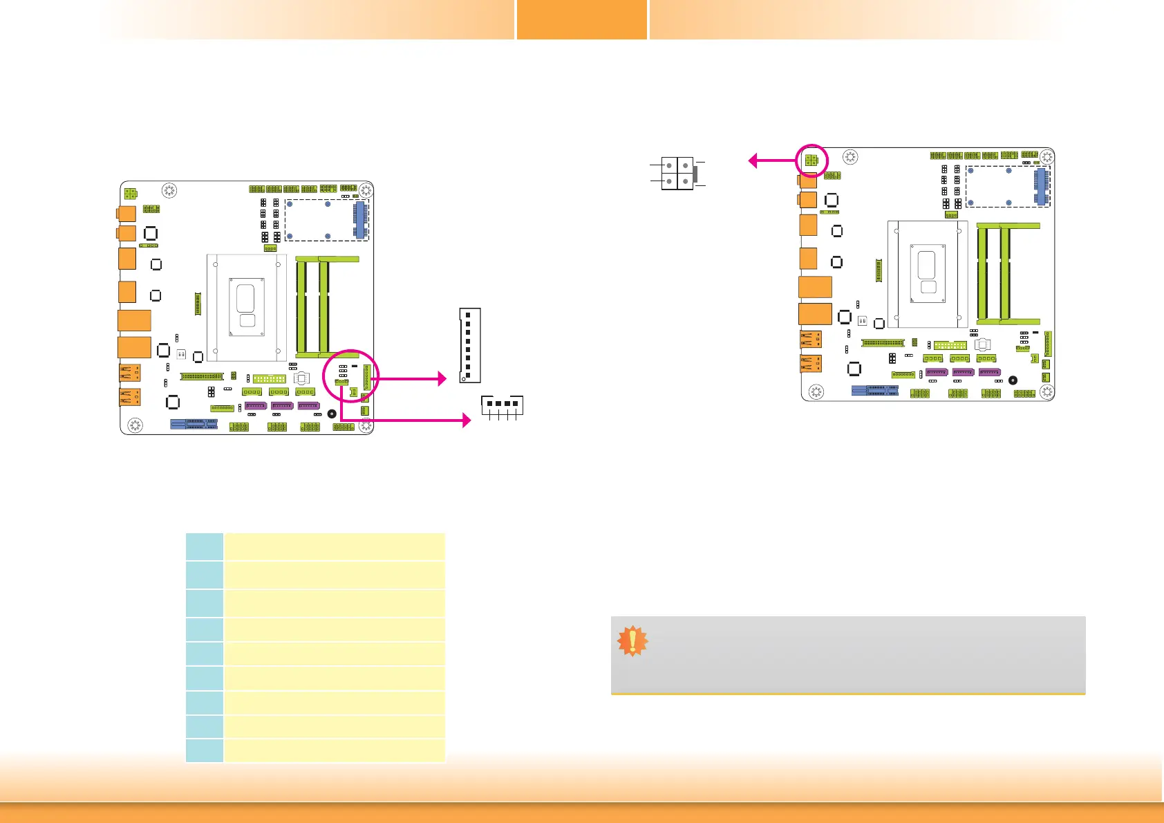
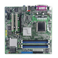
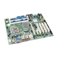
I/O Connectors
Digital I/O Connector
Digital I/O Power Connector
The 8-bit Digital I/O connector provides powering-on function to external devices that are con-
nected to the connector.
Digital I/O Connector
Pins Function
0
DIO7
1
DIO6
2
DIO5
3
DIO4
4
DIO3
5
DIO2
6
DIO1
7
DIO0
Digital I/O
1
4
+12V
Ground
5VSB
+5V
Digital I/O power
Power Connector
Use a power supply that complies with the +12V Power Supply Design Guide Version 1.1. The
4-pin +12V power connector enables the delivery of +12VDC current to the processor’s Volt-
age Regulator Module (VRM).
The power connector from the power supply unit is designed to fit the 4-pin connector in only
one orientation. Make sure to find the proper orientation before plugging the connector.
The system board requires a minimum of 300 Watt power supply to operate. Your system
configuration (CPU power, amount of memory, add-in cards, peripherals, etc.) may exceed the
minimum power requirement. To ensure that adequate power is provided, we strongly recom-
mend that you use a minimum of 400 Watt (or greater) power supply.
Important:
Insufficient power supplied to the system may result in instability or the add-in boards
and peripherals not functioning properly. Calculating the system’s approximate power
usage is important to ensure that the power supply meets the system’s consumption
requirements.
1
3
24
Ground
Ground
+12V
+12V
+12V
Power