25
Chapter 2 Hardware Installation
Chapter 2
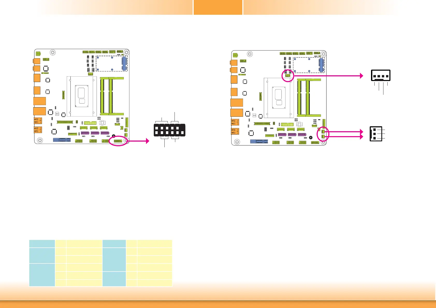
Front Panel Connector
HDD-LED - HDD LED
This LED will light when the hard drive is being accessed.
RESET-SW - Reset Switch
This switch allows you to reboot without having to power off the system.
PWR-BTN - Power Switch
This switch is used to power on or off the system.
PWR-LED - Power/Standby LED
When the system’s power is on, this LED will light. When the system is in the S1 (POS - Power
On Suspend) state, it will blink every second. When the system is in the S3 (STR - Suspend To
RAM) state, it will blink every 4 seconds.
Pin Pin Assignment Pin Pin Assignment
HDD-LED
3 HDD Power
PWR-LED
2 LED Power
5 Signal 4 LED Power
RESET-SW
7 Ground 6 Signal
9 RST Signal
PWR-BTN
8 Ground
11 N.C. 10 Signal
HDD-LED
RESET-SW
PWR-LED
PWR-BTN
12
11
2
1
Front
Panel
Cooling Fan Connectors
The fan connectors are used to connect cooling fans. The cooling fans will provide adequate
airflow throughout the chassis to prevent overheating the CPU and system board components.
BIOS Setting
The Advanced menu (“NCT6106D HW Monitor” submenu) of the BIOS will display the current
speed of the cooling fans. Refer to chapter 3 for more information.
1
3
Sense
Power
Ground
CPU Fan
System Fan 2
System Fan 1
4
1
Sense
Power
Ground
Speed Control
 Loading...