9
Chapter 2 Hardware Installation
Chapter 2
Chapter 2 - Hardware Installation
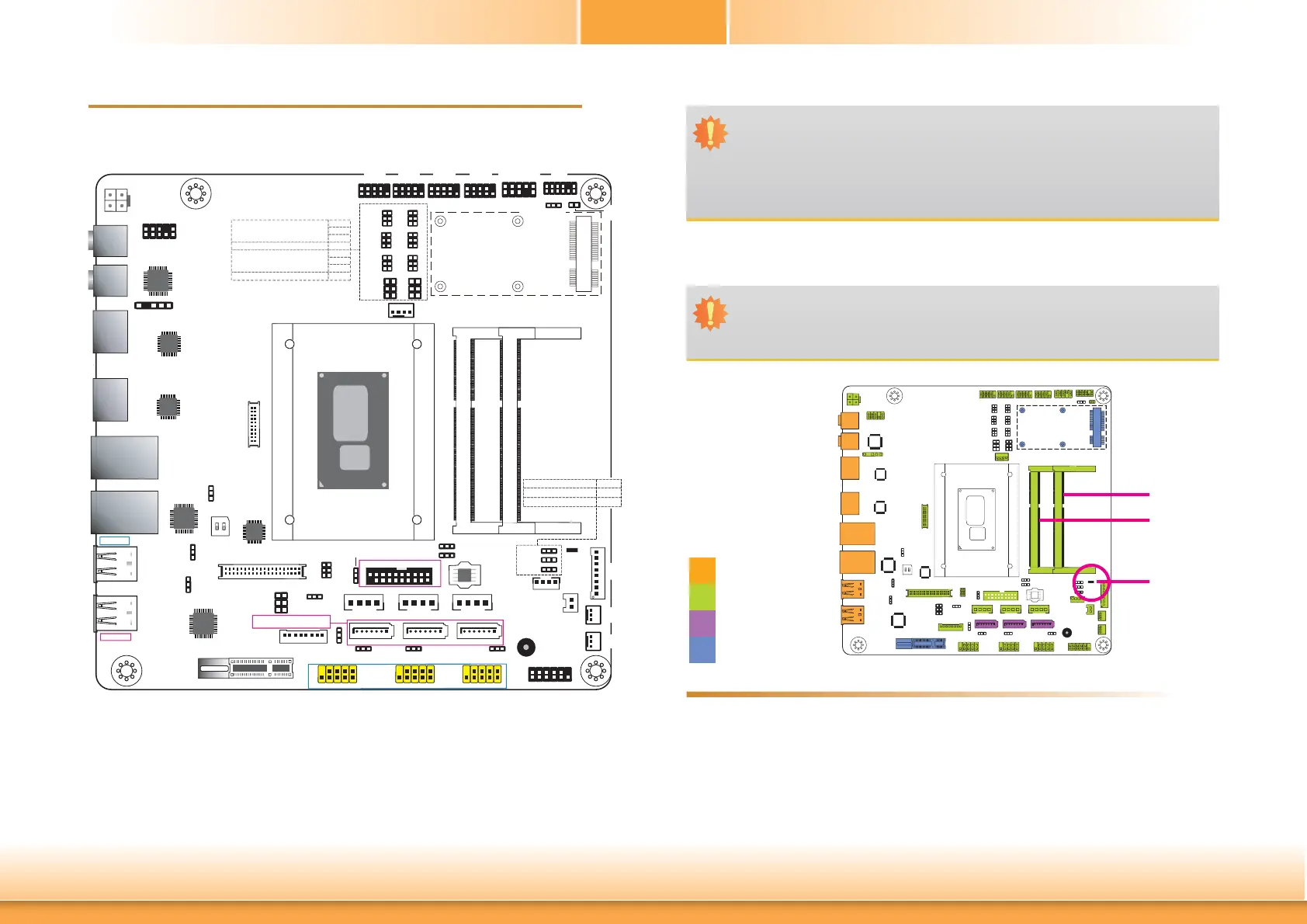
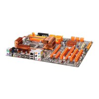
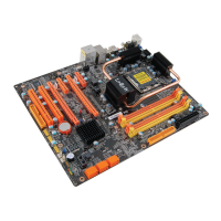
Board Layout
System Memory
Features
Important:
Electrostatic discharge (ESD) can damage your board, processor, disk drives, add-in
boards, and other components. Perform installation procedures at an ESD workstation
only. If such a station is not available, you can provide some ESD protection by wear-
ing an antistatic wrist strap and attaching it to a metal part of the system chassis. If
a wrist strap is unavailable, establish and maintain contact with the system chassis
throughout any procedures requiring ESD protection.
Important:
When the Standby Power LED lights red, it indicates that there is power on the
system board. Power-off the PC then unplug the power cord prior to installing any de-
vices. Failure to do so will cause severe damage to the motherboard and components.
Rear I/O
Onboard I/O
Storage
Expansion
• Two 204-pin DDR3L SODIMM sockets
• Supports 1333/1600MHz DDR3L SDRAM
• Supports up to 16GB system memory
• Supports dual channel memory interface
Mini PCIe
2
139
40
LVDS LCD Panel
Standby
Power LED
Buzzer
1
1
1
S/PDIF
Intel
BGA 1168
DDR3L_1 SODIMM
DDR3L_2 SODIMM
PCIe x1
1
SATA 2
1
SATA 1
1
SATA 0
SATA Power 2SATA Power 1SATA Power 0
1
2
Battery
Digital I/O Power
1
12
2
11
LPC
1
10
9
2
Front Audio
1
210
9
COM 1
1
210
9
COM 2
1
210
9
COM 3
1
210
9
COM 4
2
1
10
9
PS/2 KB/MS
1
1
USB 0-1 Power
Select (JP15)
1
1
1
LCD/Inverter Power
Select (JP19)
1 1
USB 4-5 Power
Select (JP11)
1
SATA DOM Power
Select (JP20)
2
1
10
9
2
1
10
9
1
1
Mini PCIe Signal Select (JP17)
Clear CMOS
Data (JP1)
1
1
1
(JP22)
(JP23)
(JP21)
1
2
56
21
6
5
Panel Power
Select (JP18)
56
12
56
12
(JP4)
12
56
12
56
12
56
12
56
12
56
12
56
(JP3)
(JP5)(JP5)
(JP6)
(JP7)
(JP9)
(JP10)
1
1
1
CPU Fan
+12V Power
Realtek
ALC888
LAN 2
LAN 1
HDMI 2
HDMI 1
Mic-in
Line-out
(JP8)
COM 1 RS232/422/485 Select
COM 1 RS232/Power Select
(JP3)
(JP5)
(JP6)
(JP4)
COM 2 RS232/422/485 Select
COM 2 RS232/Power Select
(JP7)
(JP9)
(JP10)
(JP8)
USB 4-5
USB 0-1
Note:
SATA0 supports SATA DOM.
SATA 3.0
1
20
10
11
USB 2-3
USB 3.0
USB 3.0
USB 7-8
USB 2.0
USB 11-12
DIO Power Select
DIO 4-7 Output State
DIO 0-3 Output State
(JP22)
(JP23)
(JP21)
USB 2.0
USB 11-12 Power
Select (JP28)
USB 7-8 Power
Select (JP29)
USB 2-3 Power
Select (JP14)
SMBus
PS/2 KB/MS
Power Select
(JP2)
Digital
I/O
eDP
(optional)
21
20 19
1
2
1
10
9
USB 9-10
USB 9-10 Power
Select (JP27)
13
24
SPI
Flash
BIOS
1
LCD/Inverter
Power
1
2
11
12
Front Panel
2
ON
1
14 14 14
Auto Power-on
Select (JP25)
System
Fan 2
System
Fan 1
NXP
PTN3460
1
Chassis
Intrusion
LVDS Channel
and bpp Select
(SW1)
Intel
WGI210AT
SMSC
USB2517
ASMedia
ASM1442
ASMedia
ASM1442
DDR3L-1
DDR3L-2
Standby
Power LED