24
2
Hardware Installation
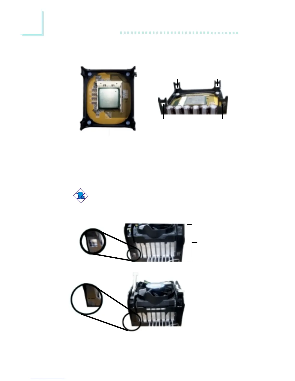
1. The system board comes with the retention module base already
installed.
Retention
module base
Retention
hole
Retention
hole
Retention
hole
Retention
hole
2. Position the fan / heat sink and retention mechanism assembly
on the CPU, then align and snap the retention legs’ hooks to the
retention holes at the 4 corners of the retention module base.
Note:
You will not be able to snap the hooks into the holes if the
fan / heat sink and retention mechanism assembly did not
fit properly onto the CPU and retention module base.
Unsnapped
Fan / heat sink
and retention
mechanism
assembly
Snapped