Maintenance Manual LS4
Issued: May 2011
Copyright DG Flugzeugbau GmbH - any copy or publishing prohibited
Manual valid with the up-to-date cover page only
5 Control surfaces
5.1 Control surface deflection limits
Rudder: to both sides 27° up to 29° or
at radius 310mm 140 up to 160 mm
12.2 in. 5.51 in. up to 6.3 in.
Aileron: up 21° up to 25° or
at radius 165mm 60 up to 71 mm
6.50 in. 2.36 in. up to 2.8 in.
down 13° up to 15° or
at radius 165mm 37 up to 43 mm
6.50 in. 1.46 in. up to 1.69 in.
Elevator: up 24° up to 30° or
at radius 148mm 359 – 369 mm from reference point
5.83 in. 14.13 in. up to 14.53 in.
down 19° - 23° or
at radius 148mm 240 – 250 mm from reference point
5.83 in. 9.45 in. up to 9.84 in.
Caution elevator: The values in mm / in. are only valid for LS4 and LS4-a.
For LS4-b the values in mm / in. are to be found in section 5.5.
You can’t compare the values for LS4 and LS4-a with the LS4-b values as with
LS4-b the reference point was moved further forward.
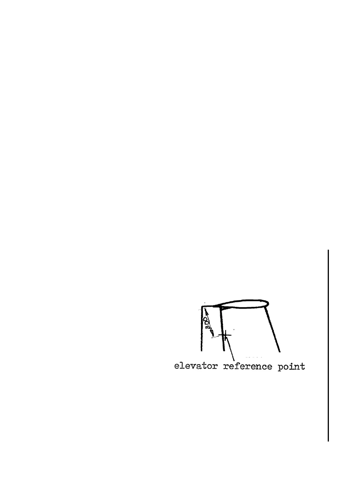
For all variants the reference point is
located 300 mm <11.81 in.> from the
elevator trailing edge at zero setting,
below the elevator and in front of the
fin trailing edge.
Note LS4-b: During LS4-b production the control surface trailing edges haven’t
been cut at the same radius., so the radius is not a fixed value.
You may determine the value from the production inspection deflections report
or by measuring.
You find the control surface tolerances in mm / in. for different radii in the
tables in section 5.5.