1 Introduction
ECO 9099 SOP05-5090F Rev.00 Effective Date: 12/20/18 Page 24 of 58
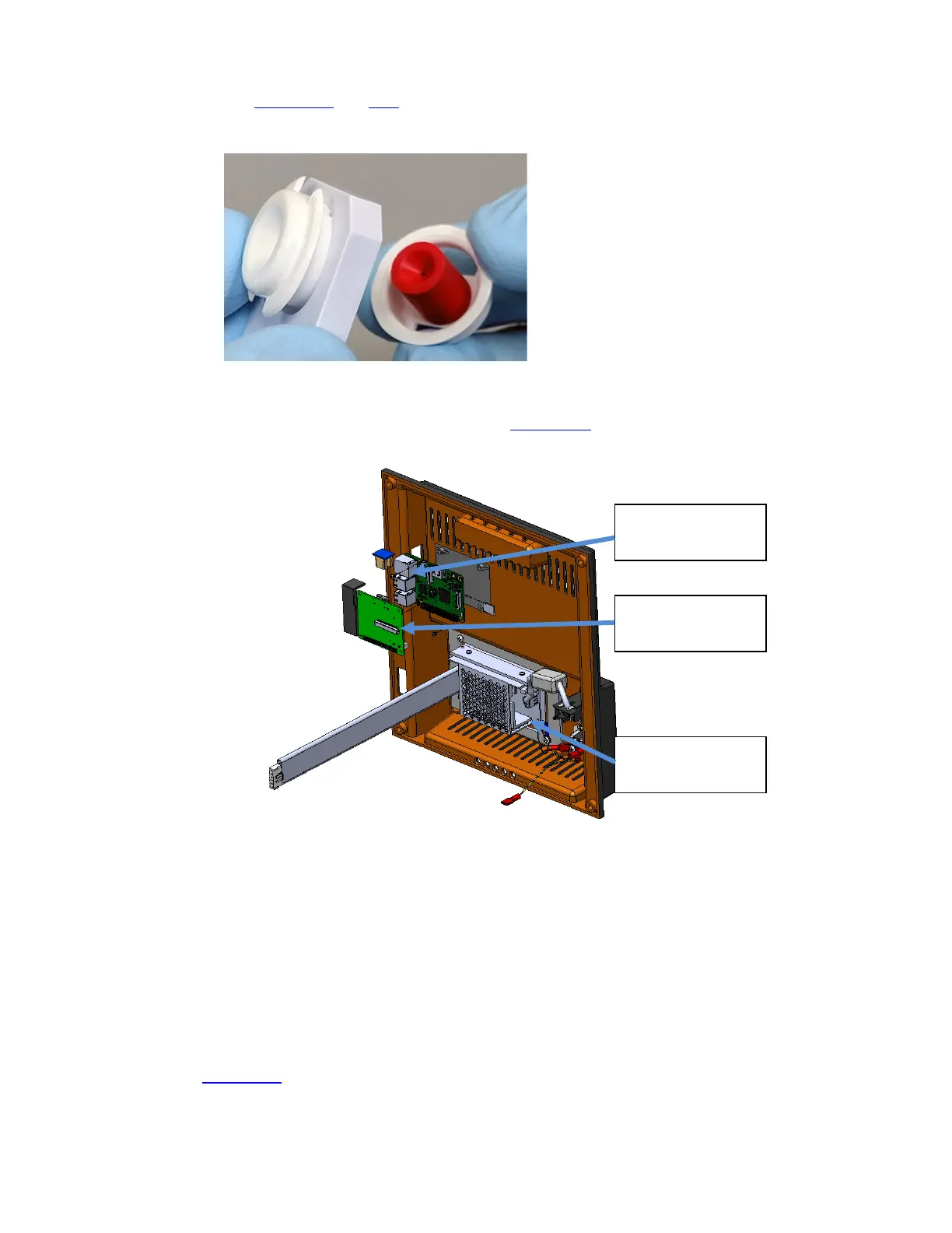
2. Press the two plastic tabs on the fill port to allow removal of the fill port from the fill port
holder. (Figure 1-26 and 1-27
)
Figure 1-27 Fill Port Removed from Holder
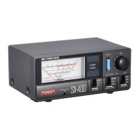
To remove the aspiration assembly Rear Panel (Figure 1-28) which contains the Power Supply,
Power Inlet Module, USB and Ethernet connectors must be removed first
Figure 1-28 Rear Case with Connectors, Power Supply
1. Ensure power is off before proceeding.
2. Disconnect RS232 cable if attached.
3. Disengage the 4 screws in the corners of the back case.
4. Move the back case a few inches away from the chassis.
5. Disconnect cables and wires so that the rear case can be separated from the front case.
(Figure 1-29
)
a. Disconnect the communication ribbon cable from the Communication Board on the
back panel leading to the Display Board.
Ethernet. USB Ports
Com Board Ribbon
Cable connector
Power Supply