1 Introduction
ECO 9099 SOP05-5090F Rev.00 Effective Date: 12/20/18 Page 25 of 58
b. Disconnect the power cable attached to the CPU board by depressing the locking clip
on the left side of the connector and gently pulling the power cable out.
Once the CPU board has been removed, the Aspiration Sub-Assembly can be removed.
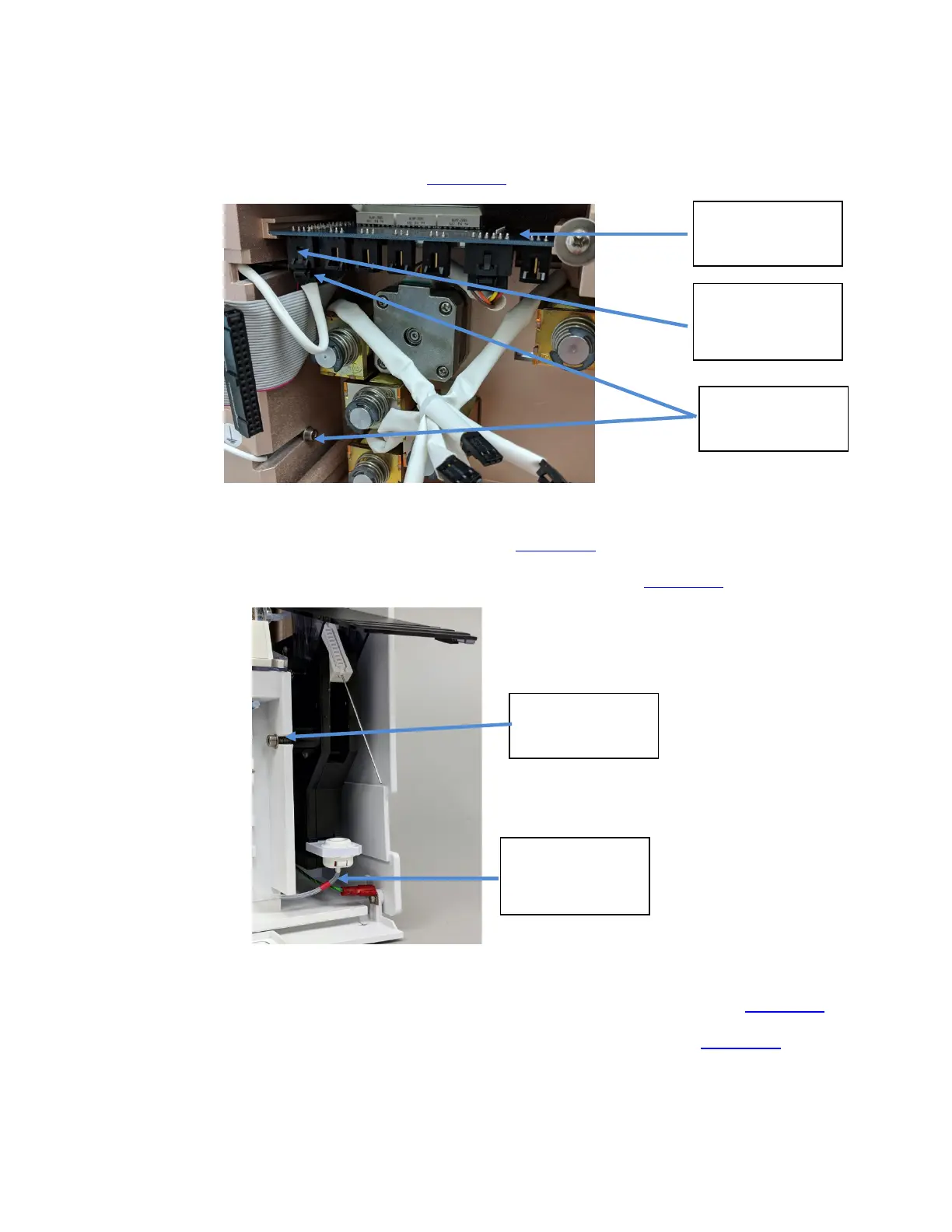
1. The cable on the far left side of the valve board is the aspiration assembly connector. Press
the connector tab to disconnect. (Figure 1-29
)
Figure 1-29 Connectors and cables on CPU Board
6. Remove the two rear screws using a hex key (Figure 1-29)
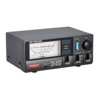
7. Then, remove the front securing screw using the same hex key. (Figure 1-30)
Figure 1-30 Front Hex Screw for Aspiration Sub-Assembly
10. Check that the sample intake tubing is disconnected from the sample detector. (Figure 1-25)
11. Disconnect the reagent supply tubing (red tag) from beneath the fill port. (Figure 1-30)
12. The aspiration assembly can now be removed from the front of the analyzer for replacement.
Valve Board
Aspiration Sub-
Assembly
Connector
Rear Hex
Screw
Front Hex
Screw
Reagent Supply
Tubing (tagged
red)