OPERATOR’S MANUAL
PM300, PM332, PM400 Planter Monitors
11001-1372-201702 Rev B
QUICK START GUIDE / 11
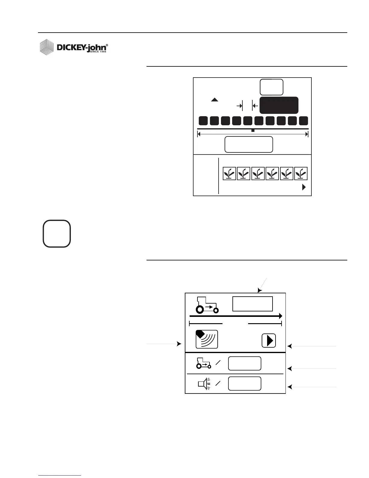
Figure 5
Row Spacing Screen
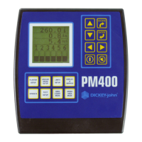
GROUND SPEED CONFIGURATION
To perform Ground Speed Configuration, select the Ground Speed Setup
key. The Ground Speed Setup screen will display (refer to Figure 6).
Figure 6
Ground Speed Setup Screen
123
#
in
10.00
ft
I/O
ROW SPACING
8
1 2 3 5 6
4
15.0
6096
0.0
mph
400 ft
=
0.0
mph
=
Start symbol (will
change to
Stop symbol when
test begins
Manual ground
speed (optional)
Maximum speed
alarm (optional)
# of pulses in 400 ft.
Ground Speed
Source
(Radar or
Reluctance)
Ground Speed Setup key