OPERATOR’S MANUAL
PM300, PM332, PM400 Planter Monitors
11001-1372-201702 Rev B
INTRODUCTION / 3
INTRODUCTION
SYSTEM OVERVIEW
The DICKEY-john PM300, PM332, and PM400 Planter Monitors offer
features to monitor 16, 32, and 36 rows, respectively. The units monitor
seed or fertilizer rows, two hopper levels, and a frequency input (shaft, fan,
or flow). The monitors are compatible with DICKEY-john seed, flow, hopper
level, and gear sensors. The units store all configuration data in nonvolatile
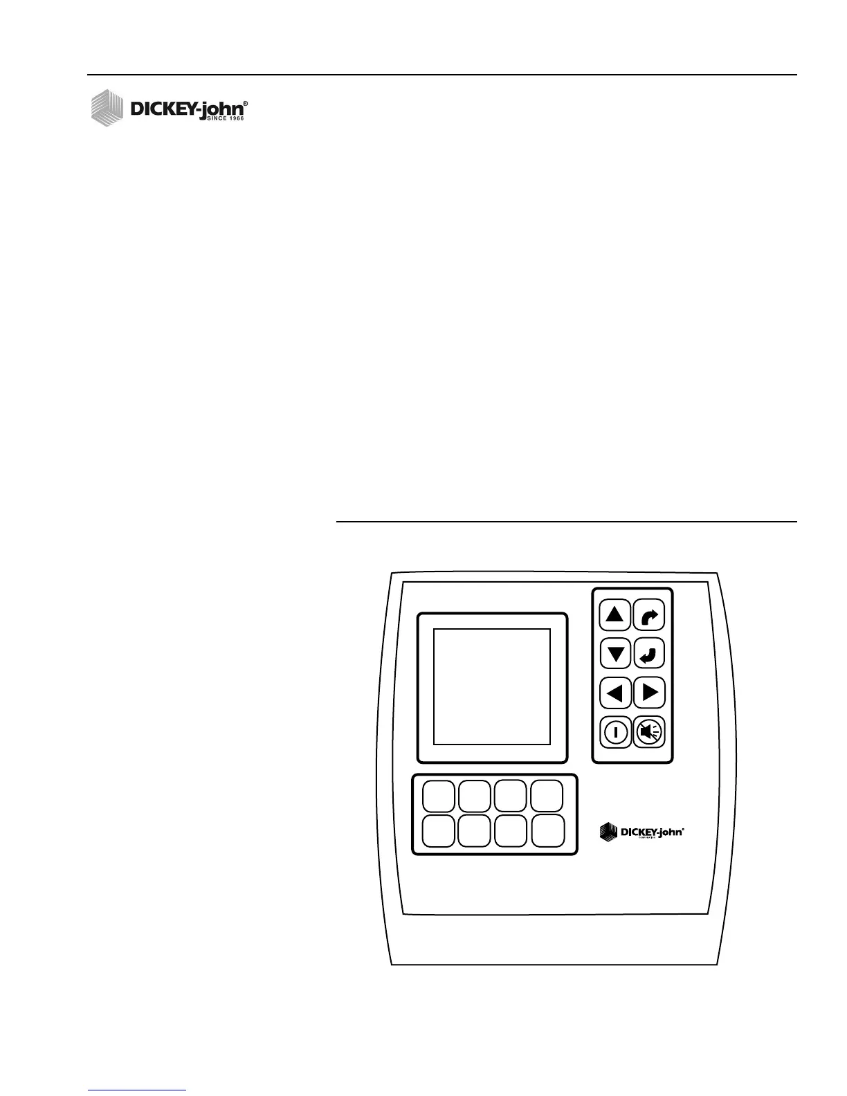
memory, retaining information even when disconnected from power. Figure
1 provides an illustration of a generic console.
The PM300, PM332, and PM400 are designed to meet the custom needs of
individual users. The display may be configured to output a comprehensive
set of planter parameters. The user selects the type and number of
parameters to be monitored. Choices may be as simple as monitoring
population and field area or may be more complex. Similarly, blink or fail
mode information may be viewed as a bar graph, gauge, or symbol.
Information may be viewed in large format (for ease of viewing), or small
format (for entire planter view). Auto-scrolling and arrow key override are
used to maintain control of real-time information required by the user.
Figure 1
PM300, PM332, and PM400
PMXXX
ENTER
ESCAPE
ACCY
SETUP
DISPLAY
&
SERVICE
GROUND
SPEED
SETUP
LIMITS
SETUP
OPERATE
PLANTER
SETUP
SPEED
AREA
MODE
SEED
COUNT
MODE