OPERATOR’S MANUAL
PM300, PM332, PM400 Planter Monitors
11001-1372-201702 Rev B
26 / ADVANCED SETUP
2. Verify that the speed matches the vehicle’s speedometer or
re-measure the 400-foot distance.
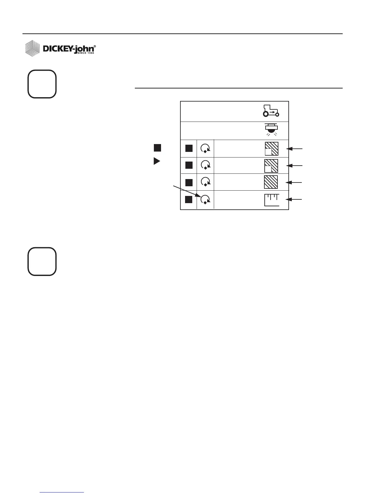
Figure 15
Speed Area Mode Screen
ACCESSORY SETUP (OPTIONAL)
To add an auxiliary sensor and its performance characteristics (calibration
values, limits, etc.) to the monitoring inputs, it must be activated by entering
a calibration constant. If minimum or maximum alarms are desired, the
limits may be added to the calibrated sensors. A fan, shaft, or flow sensor
may be monitored with HI and/or LOW alarms or no alarm values. Refer to
Figure 16.
1
5.1
0.0
2
17.217.2
1 2
14.1
31.4
0.0
Field Area 1
Field Area 2
Total Area
Distance
Reset
Counter
Stop
Start