5
4. CONNECTING THE VALVE WIRES TO THE CONTROLLER
1. Select and use suitable 16, 18 or
20-gauge direct burial, strand gauge
sprinkler wire between the valve
location and the controller. 18-gauge
direct burial, strand multi-color coded
wire is recommended.
2. Each valve connects to the controller
using two wires, hot wire (color-code)
and common wire (white). The common
wire (white) is shared with all valves.
At the valve, connect the common wire
to either solenoid wire of all valves using waterproof wire splice connectors. Connect
each color code wire to the remaining wire of each valve using waterproof wire splice
connections. (see figure 1)
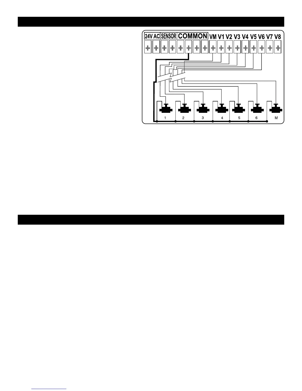
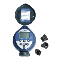
3. Remove the cover from controller to access the terminal strip area. (see figure 1)
4. Connect the valves common wire to one of the four (4) “COM” common terminals
available. Connect each valve color-code wire to the appropriate station # on the controller
terminal. (see figure 1)
NOTE: Make sure the wires connections to the terminals are tight and firm.
WARNING: Do not connect more then one valve wire to each terminal.
5. CONNECTING A MASTER VALVE OR PUMP START RELAY
24 VAC master valves can be attached at the inlet to the irrigation system. The master valve
will automatically open with the first valves and will close automatically when the last valve
is closed. The master valve is shown on the controller display by the letter: M and on the
connections panel by the letters VM.
MASTER VALVE
a. If master valve is used, connect the common wire to one of the four (4) “COM”
terminals available and the valve color-coded wire to the VM terminal. (see figure 1)
PUMP
a. If pump is used, mount the controller a minimum of 15 feet away from a pump start
relay and the pump.
b. Connect either wire from the pump start relay to the controller terminal “VM” and
connect other wire to one of the four (4) “COM” common terminals available.
NOTE: To operate a pump, a pump start relay must be used. Do not connect controller
directly to pump start, it can damage the controller. Connecting the controller to a
pump is to be performed by a qualified electrician only.
Figure 1