EasyManuals Logo
Home>Digi>Control Unit>ConnectCore

Digi ConnectCore User Manual

Digi ConnectCore
151 pages
To Next Page IconTo Next Page
To Previous Page IconTo Previous Page
Page #116 background imageLoading...
Page #116 background image
ConnectCore for i.MX51
©2011DigiInternational,Inc. 116
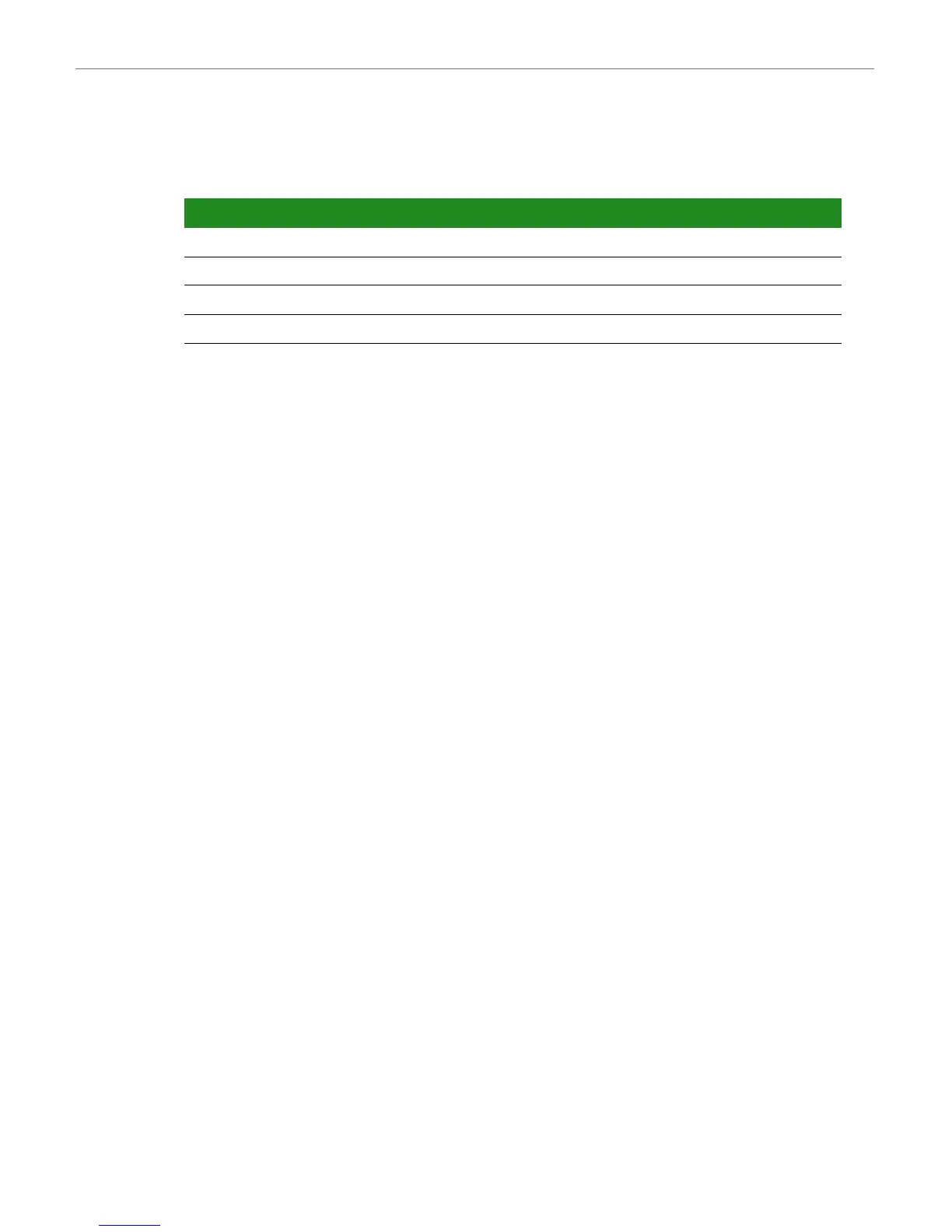
The table below shows the GPIO signal assigned to the user interface, and the jumpers used
to enable/disable the buttons and LEDs:
Signal GPIO Jumper Comment
USER_BUTTON1 GPIO3_6 J28 10K pull-up to +2.775V on the development board
USER_LED1# GPIO3_10 J16
USER_BUTTON2 GPIO1_1 J29 10K pull-up to +2.775V on the development board
USER_LED2# GPIO3_9 J9
Downloaded from Elcodis.com electronic components distributor

Table of Contents

Other manuals for Digi ConnectCore

Questions and Answers:

Question and Answer IconNeed help?

Do you have a question about the Digi ConnectCore and is the answer not in the manual?

Digi ConnectCore Specifications

General IconGeneral
BrandDigi
ModelConnectCore
CategoryControl Unit
LanguageEnglish

Related product manuals