ConnectCore for i.MX51
©2011DigiInternational,Inc. 131
Electrical Characteristics
Charger vs. Battery
The ConnectCore for i.MX51 can be supplied solely either through the battery input or also
through the charger input. When using solely the charger input, and when no battery is
connected to VLIO, the ConnectCore for i.MX51 won't be functional at temperatures below -
20
° C. This is due to the internal state machine of the on-module PMIC (Power Management
IC).
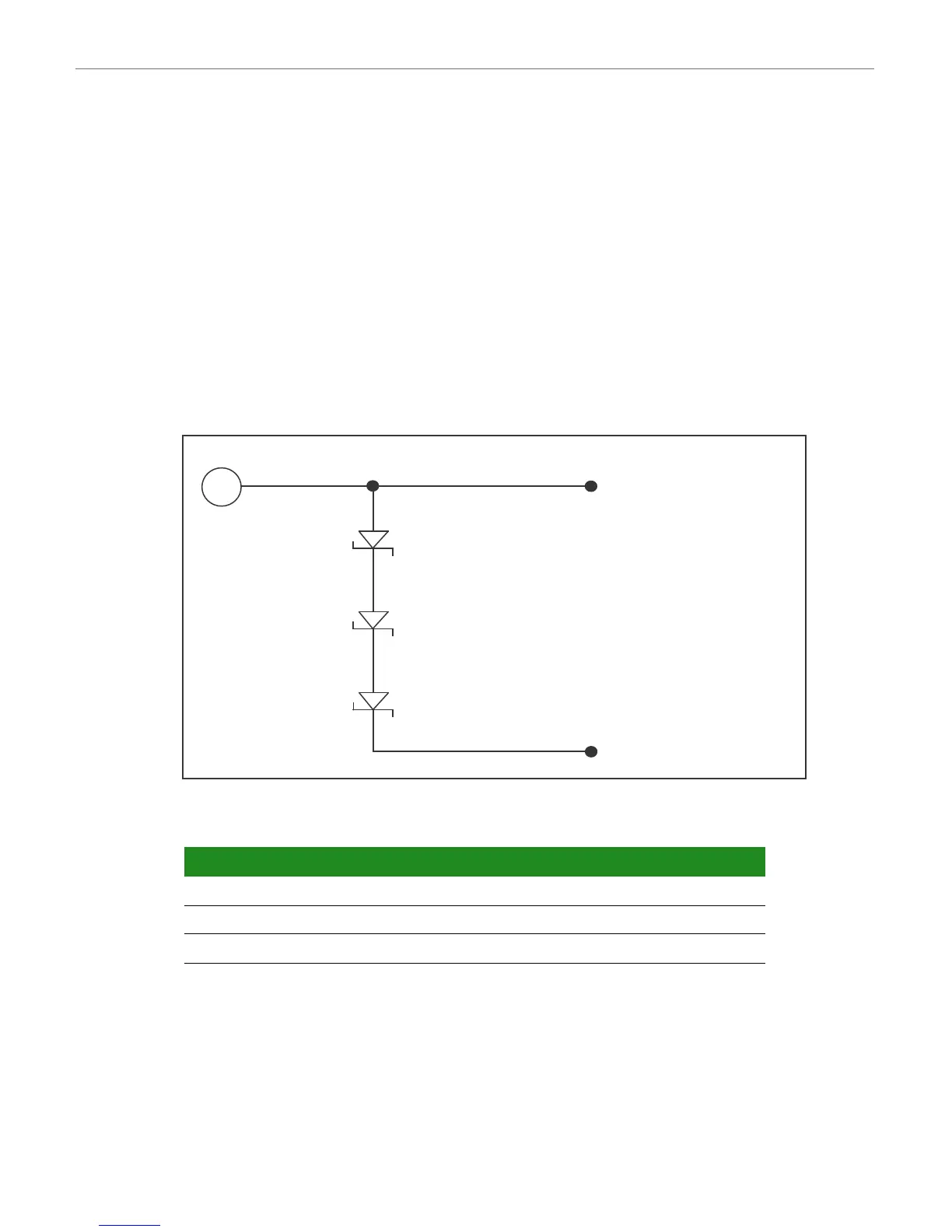
To override this limitation, a battery voltage must be generated on the carrier board.
Different options are available for simulating a battery voltage - below is one example, based
on three Schottky diodes in series.
Supply Voltages
Supply Current
The following table provides current draw guidance utilizing the power management
capabilities of the module. The module variant used for the measurements works at 800MHz,
with 512 MB NAND Flash, 512 MB DDR2, dual Ethernet, WLAN, and accelerometer. A Windows
Embedded CE kernel with power management capabilities has been used to make the current
Parameter Symbol Min Typ Max Unit
Battery Input VLIO 3.4 3.7 4.8 V
Charger Input VCHRG 3.4 5 20 V
Coin cell Input for RTC VCC_COINCELL 2.5 3 3.6 V
Connect to VCHRG
+ 5V
SS36
D1
SS36
D2
SS36
D3
Connect to VLIO
Downloaded from Elcodis.com electronic components distributor