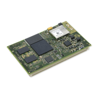
ConnectCore for i.MX51
©2011DigiInternational,Inc. 63
Module Power Source, P29
When set on positions 1-2, the 3.3V supply of the development board is generated on the
+3.3V power regulator (U50).
When set on positions 2-3, the +3.3V supply of the development board is generated on the
module.
LED 1, J16
When set, enables the User LED 1 (LE51) to show the status of this signal (on if low).
LED 2, J9
When set, enables the User LED 2 (LE49) to show the status of this signal (on if low).
Button 1, J28
When set, enables the User Button 1 (S3).
Button 2, J29
When set, enables the User Button 2 (S5).
UART3 / XBee Selection, J30 and J31
The UART 3 port is shared on the development board between the XBee module socket and
the UART 3 connector (X19).
When J30 and J31 are set to positions 1-2, the UART 3 on the connector (X19) can be used.
When J30 and J31 are set to positions 2-3, the XBee module socket can be used.
WLAN Disable, J17
When set, this jumper disables the WLAN interface on the module.
Touch Selection, J20
When set, an external SPI touch screen controller is configured for the LCD 1 interface and
the internal analog touch screen controller (on module) is configured for the LCD 2 interface.
When removed, an internal touch screen controller is configured for the LCD 2 interface, and
the internal analog touch screen controller (on module) is configured for the LCD 1 interface.
Downloaded from Elcodis.com electronic components distributor

 Loading...