HI, MI, WI-700 service manual
Issue 9 04/2020
Contents
1 - Installation
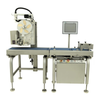
About the HI-700 evo, HI-700W, MI-700 & WI-700 1-2
Shipment of machine 1-5
Safety 1-6
Moving the machine 1-8
Rated operation conditions 1-9
Programming note 1-9
Installation requirements 1-10
Installation - machine feet 1-11
Fitting labeller to labeller arm 1-11
Connections inside electrical cabinet 1-12
Outfeed conveyor connection 1-17
Additional conveyor connection 1-18
Labeller position adjustment 1-18
Touch applicator transport packaging 1-18
Load cell transit screw 1-19
Setting corner overload stops 1-22
Switching on/off machine & conveyors 1-23
Thermal head heater connection (Signature labeller) 1-23
Loading labels - Signature top labeller 1-24
Loading labels - Classic labeller 1-28
2 - Component parts
The electrical cabinet 2-2
Items inside the electrical cabinet 2-3
PC main board - type LV-67P 2-4
Hard drive 2-7
Battery 2-8
Power supply LS75-15-15VDC 2-9
UPS board 2-10
5 port Ethernet switch 2-11
Relay 5v 2-12
A/D power supply 2-13
A/D unit 2-14
24v power supply 2-16
Omron PLC 2-17
Motor driver board 2-20
Infeed speed control 2-22
Primary fuse 2-23
Control fuse 2-23
Cooling fans 2-24
Software licence dongle 2-24
Pack sensors - fibre optic 2-25
Opto-electric (Wenglor) 2-26
Conveyors & motors (click-in type) 2-27
Outfeed conveyor when base labeller is fitted 2-29
Load cell 2-31
Touch screen 12.1’’ 2-34
Touch screen `15’’ 2-37
Labeller - Signature 2-38
Classic type 2-39
Thermal head 2-40
Wear strip & silicone tube (Signature) 2-41
Platen roller option (Signature) 2-42
Thermal head heaters (Signature) 2-43
Labeller board 2-44
Labeller sensor I/F board 2-45
Power supply 5.35v 2-46
Power supply 25v 2-47
Power supply 42v 2-48
Stepper motor 2-49