HI, MI, WI-700 service manual - 2 - component parts
2-18 Issue 9 04/2020
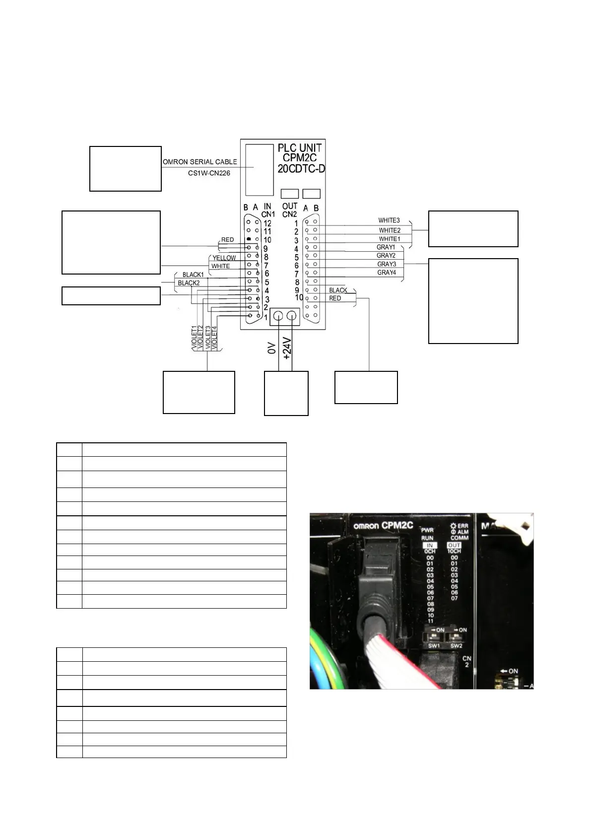
PLC unit CPM2C
Refer to the electrical drawings for more details on the connection to and from this unit.
Serial connec-
tion to pc main
board
Red=24v term rail
Yellow=start button
White=stop button
Black1(violet)=sensor 1
Black2(green)=sensor2
Emergency stop (blue)
To speed con-
trol board –
alarm out
24V
from
PA201
24v terminal
rail
Grey1= blow signal-
not required. See
note on previous
page.
Grey2= reject 1
Grey3= reject 2
Grey4= reject 3
To speed control
board - run/brake
This unit has indication lights on its front display
to indicate the input/outputs that are happening at
the given time.
00 Sensor 1 (infeed)
01 Sensor 2 (scale)
02 Emergency stop switch
03 Sensor 2 (scale)
04 Sensor 1 (infeed)
05 Conveyor stop button
06 Conveyor start button
07 Not used
08 Sub infeed motor driver
09 Infeed motor driver
10 Scale motor driver
11 Outfeed motor driver
Inputs
00 Infeed conveyor run
01 Scale conveyor run
02 Outfeed conveyor run
03 Blow signal for labeller- not used, see note
04 Rejector 1 (RJ1)
05 Rejector 2 (RJ2)
06 Rejector 3 (RJ3)
07 Not used
Outputs