HI, MI, WI-700 service manual - 2 - component parts
2-19 Issue 9 04/2020
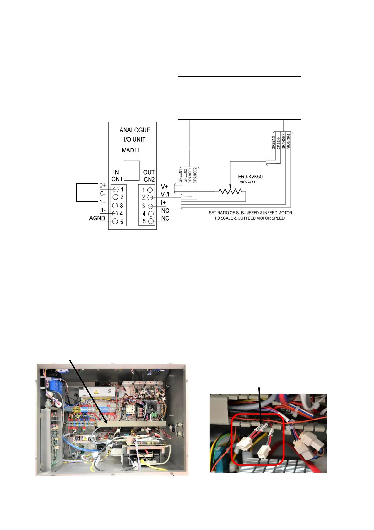
MAD11 analogue unit
Refer to the electrical drawings for more details on the connection to and from this unit.
To Motor speed control boards
Green to VRM
Orange to VRL
Note: infeed output goes through a
2K5Poteneometer for separate speed adjustment
Not
used
The final speed of the conveyors is controlled by the output voltage from CN2; therefore this voltage is
variable depending on the conveyor speed selected.
The range the voltage will be is between 1v and 5v (1v being slowest speed, 5v being max speed)
This voltage is connected to each motor speed control board at VRM (green) and VRL (orange).
The 2K5POT is used to adjust the sub-infeed & infeed to a slower speed that the set conveyor ppm. This is
useful to extend a larger gap between packs at the infeed stage.
Note: if a sub-infeed is fitted they may be an independent pot for each infeed.
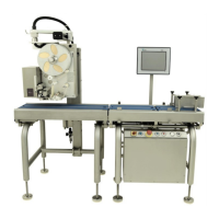
Rejector signal output
If a rejector is to be connected to the HI there are three outputs from the PLC each having a 2 way Molex
connector fitted. The connectors are marked as REJ 1, REJ 2 & REJ 3.
Remove or slide left this trunking cover
REJ 1, REJ 2 & REJ 3 are
located here