Overview Pin signals
XBee/XBee-PRO ZigBee RF Modules User Guide 16
Through-hole single-row receptacles - Mill-Max P/N: 831-43-0101-10-001000
Surface-mount double-row receptacles - Century Interconnect P/N: CPRMSL20-D-0-1 (or equivalent)
Surface-mount single-row receptacles - Samtec P/N: SMM-110-02-SM-S
Note We also recommend printing an outline of the module on the board to indicate the orientation the
module should be mounted.
Pin signals
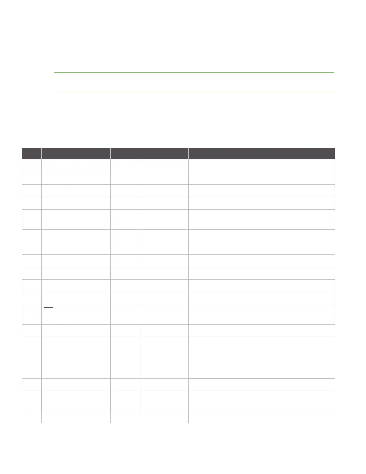
The following table shows the pin assignments for the XBee/XBee-PRO Modules (low-asserted signals are
distinguished with a horizontal line above signal name).Signal direction is specified with respect to the module.
See Design notes on page 18 for details on pin connections.
Pin # Name Direction Default State Description
1VCC - - Power supply
2 DOUT Output Output UART Data Out
3 DIN / CONFIG
Input Input UART Data In
4 DIO12 Both Disabled Digital I/O 12
5 RESET Both Open-Collector
with pull-up
Module Reset (reset pulse must be at least 200 ns)
6 RSSI PWM / DIO10 Both Output RX Signal Strength Indicator / Digital IO
7 DIO11 Both Input Digital I/O 11
8 [reserved] - Disabled Do not connect
9DTR
/ SLEEP_RQ/ DIO8 Both Input Pin Sleep Control Line or Digital IO 8
10 GND - - Ground
11 DIO4 Both Disabled Digital I/O 4
12 CTS
/ DIO7 Both Output Clear-to-Send Flow Control or Digital I/O 7. CTS, if
enabled, is an output.
13 ON / SLEEP
Output Output Module Status Indicator or Digital I/O 9
14 VREF Input - Not used for EM250. Used for programmable secondary
processor.
For compatibility with other XBee modules, we
recommend connecting this pin voltage reference if
Analog sampling is desired. Otherwise, connect to GND.
15 Associate / DIO5 Both Output Associated Indicator, Digital I/O 5
16 RTS
/ DIO6 Both Input Request-to-Send Flow Control, Digital I/O 6. RTS, if
enabled, is an input.
17 AD3 / DIO3 Both Disabled Analog Input 3 or Digital I/O 3