Module support Writing custom firmware
XBee/XBee-PRO ZigBee RF Modules User Guide 178
CAUTION! If programming firmware through the SIF interface, be aware that uploading firmware through the
SIF header can potentially erase the XBee bootloader. If this happens, serial firmware updates will
not work.
The pinout for the SIF headers are shown in Overview on page 9.
Writing custom firmware
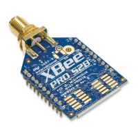
The XBee/XBee-PRO module can be used as a hardware development platform for the EM250. Custom firmware
images can be developed around the EmberZNet 2.5.x and 3.x mesh stacks (for the EM250) and uploaded to the
XBee.
CAUTION! If programming firmware through the SIF interface, be aware that uploading firmware through the
SIF header can potentially erase the XBee bootloader. If this happens, serial firmware updates will
not work.
Regulatory compliance
XBee modules are certified for operation on all 16 channels. The EM250 output power can be configured up to
3dBm with boost mode enabled.
XBee-PRO modules are certified for operation on 14 of the 16 band channels (channels 11 - 24). The scan channels
mask of XBee-PRO devices must be set in the application to disable the upper two channels (for example
0x01FFF800). The XBee-PRO contains power compensation circuitry to adjust the output power near 18dBm or
10dBm depending on the part number. For best results, the EM250 should be configured with an output power
level of 0dBm (or -2dBm if boost mode is enabled). The end product is responsible to adhere to these
requirements.
Enabling GPIO 1 and 2
Most of the remaining sections in this section describe how to configure GPIO 1 and 2 to function correctly in
custom applications that run on the XBee and XBee-PRO modules. In order for GPIO pins 1 and 2 to be
configurable, the application must set the GPIO_CFG register to enable GPIO 1 and 2. Bits 4 - 7 in the GPIO_CFG
register control the functionality of various GPIO lines. The following table lists values for these bits that enable
GPIO 1 and 2. Other functionality is affected by these settings. See the EM250 datasheet from Ember for a
complete listing of functionality.
Example 1
The following code enables GPIO 0, 1, 2, 3, 9, 10, 11, and 12 and maintains all other GPIO_CFG bits.
int16u x;
x = GPIO_CFG;
x &= (0xFF0F); // Clear bits 4 - 7
GPIO_CFG[7:4]Enabled Functionality Enabled Functionality
0000 GPIO 0, 1, 2, 3, 9, 10, 11, 12
0111 0111GPIO 0, 1, 2, 3, 12
1010 GPIO 0, 1, 2, 3
1101 GPIO 0, 1, 2, 3, 11, 12

 Loading...