Overview Pin signals
XBee/XBee-PRO ZigBee RF Modules User Guide 17
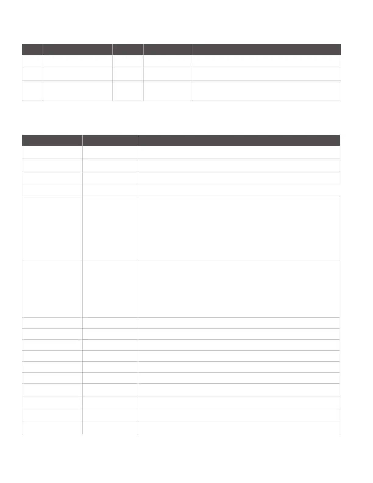
EM250 pin mappings
The following table shows how the EM250 pins are used on the device.
18 AD2 / DIO2 Both Disabled Analog Input 2 or Digital I/O 2
19 AD1 / DIO1 Both Disabled Analog Input 1 or Digital I/O 1
20 AD0 / DIO0 /
Commissioning Button
Both Disabled Analog Input 0, Digital IO 0, or Commissioning Button
Pin # Name Direction Default State Description
EM250 Pin Number XBee Pin Number Other Usage
13 (Reset)
5
1
Connected to pin 8 on 2x5 SIF header.
19 (GPIO 11)
16
1
20 (GPIO 12)
12
1
21 (GPIO 0)
15
22 (GPIO 1) XBee
Tied to ground (module identification)
XBee-PRO (S2)
Low-asserting shutdown line for output power compensation
circuitry.
XBee-PRO (S2B)
Used to communicate with Temp Sensor and control Shutdown
for low power mode.
24 (GPIO 2) XBee
Not connected. Configured as output low.
XBee-PRO (S2)
Powers the output power compensation circuitry.
XBee-PRO (S2B)
Used to communicate with Temp Sensor and control Shutdown
for low power mode.
25 (GPIO 3)
13
26 (GPIO 4 / ADC 0)
20
Connected to pin 9 on 2x5 SIF header.
27 (GPIO 5 / ADC 1)
19
Connected to pin 10 on 2x5 SIF header.
29 (GPIO 6 /ADC 2)
18
30 (GPIO 7 / ADC 3
17
31 (GPIO 8)
4
32 (GPIO 9)
2
1
33 (GPIO 10)
3
1
34 (SIF_CLK) Connected to pin 6 on 2x5 SIF header.
35 (SIF_MISO) Connected to pin 2 on 2x5 SIF header.