8
The condensate pipe should not run
into sewer pipe as fumes may travel
into the heat pump and cause
corrosion to the evaporator coil.
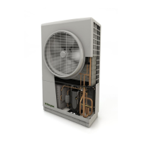
The heat pump must be fixed onto a
level, stable base that is capable of
withstanding the unit’s weight of
130kg, with a minimum of 30mm
clearance around all sides of the
heat pump (recommended minimum
L x W x D = 1000 x 470 x 100mm).
It can be secured with M10 anchor
bolts, using the fixing holes shown
in figure 3.
Ideally the heat pump should be
located close to the property.
Positioning of the heat pump at a
distance from the property will
result in the need for extra insulated
pipe, which will lead to extra cost,
and result in additional heat losses.
3.6 Plumbing –Preparation
When selecting piping to install with the
heat pump please ensure:
The pipe sizes are adequate to allow
correct minimum water flow rate
through the heat pump.
Table 1: Maximum length of copper pipe
The pipe lengths given in table 1
include the straight length of the
piping and all elbows. The
equivalent straight length (L) of
each elbow is found by multiplying
the outer diameter of the pipe (D)
by 30:
External pipes should be adequately
insulated with vapour resistant
insulation and protected against
damage to prevent excessive heat
losses. All joints should be suitably
sealed and exposed pipework must
be avoided.
Existing hot water systems should
be flushed prior to connection to the
heat pump to remove all
contaminants and impurities, in
accordance with the latest version of
MIS 3005.
Make the water flow and return
pipes positioned correctly for
connection to the heat pump as
shown on the label in figure 4 and
on the back of the heat pump.
Isolation valves, supplied in the
Dimplex heat pump hydraulics pack,
allow the strainer to be removed
and cleaned without having to drain
the system (non-return valve and
ball valve with strainer). Installation
of these valves is discussed in more
detail section 5.2.
If heat emitters consist of underfloor
heating and higher temperature
heat emitters, a mixing valve must
be used to prevent high
temperature water entering the
underfloor heating manifold.