11
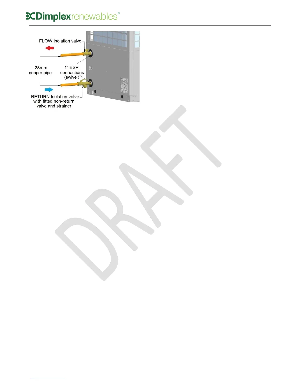
Figure 7: Flow and return valves
The non-return valve built into
‘1062815CR’ allows the strainer to
be cleaned without draining the
system, by simply closing the flow
and return valves and removing the
strainer. The only water that is lost
will be that in the return valve.
System pressure must be checked
once valves are re-opened.
Direct condensate drain pipe to soak
away or drain, as illustrated in
figure 3 in section 3.5.2.
All piping must be properly
insulated.
4.3 Electrical connections
The heat pump system consists of the
heat pump, wiring centre and user
interface. If a Dimplex A Class cylinder
is also purchased, the wiring centre is
built into the cyinder. The user interface
contains a thermostat and is sufficient if
one heating zone is present.
Optional, additional UI’s, temperature
probes or room thermostats are
required for additional heating zones.
Figure 8 (a) – (c) shows the wiring
configuration of the 3 different
installation options (outlined in section
2: Scope of Delivery, at the beginning
of this manual).