13
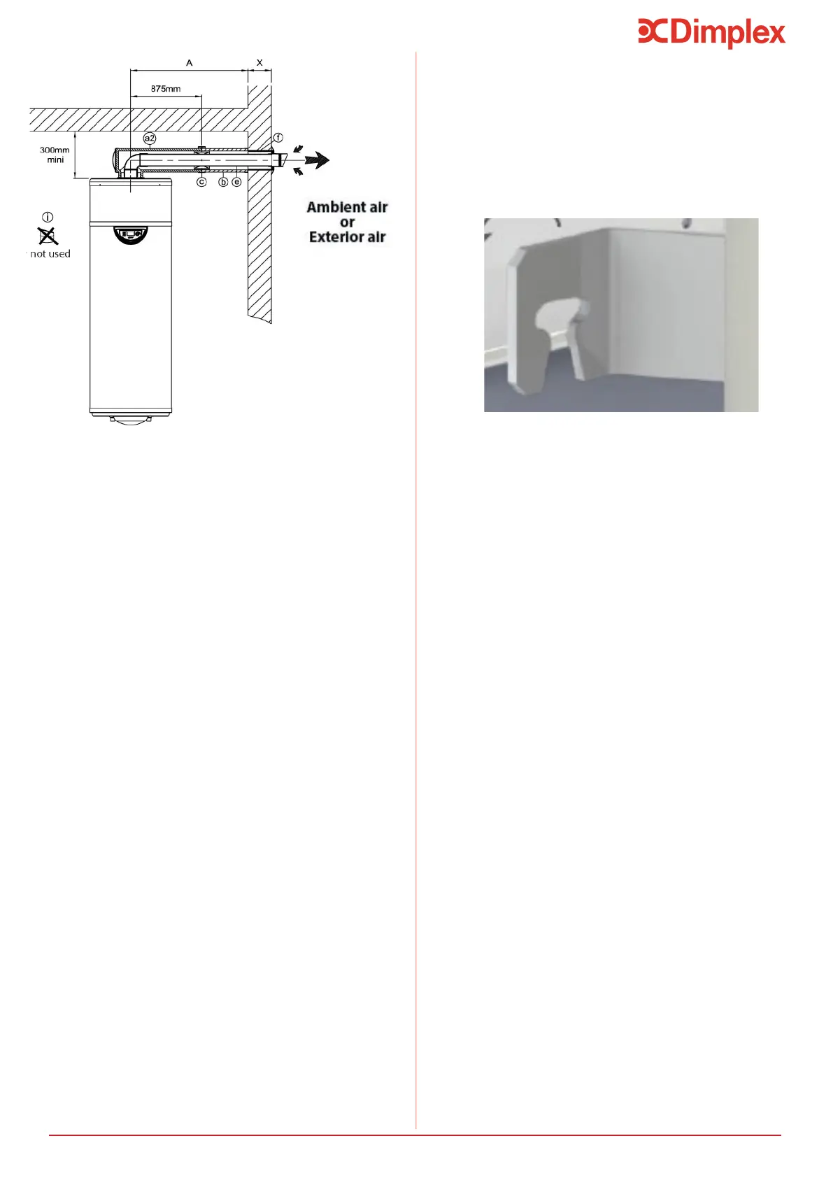
Figure 12: Distanced access installation
1.Cut the Ø125 PVC pipe to (X + 25mm).
2. Glue it into the air duct nozzle.
3. Position the Ø125 wall joint.
4. Pass the assembled air duct nozzle through the wall
from the outside.
5. Direct the air duct nozzle upwards as indicated on the
diagram.
6. The Ø125PVC pipe should overlap by about 25mm on
the inside.
7. Mark the direction of the air duct nozzle on the inside by
marking the top of the Ø125 pipe.
against the wall at the same time.
9. Cut the Ø80 PVC pipe to (A + X - 30mm).
10. Cut the insulated extension pipe to (A-875mm).
11. Insert the Ø80 PVC pipe into the insulated extension
pipe.
12. Fix the insulated extension pipe to the insulated elbow
using a connecting sleeve.
13. Remove the cover parts from the insulated elbow.
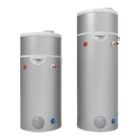
6.9 Fixing
Upon completion of the ducting installation, the product
must be fastened to the adjacent wall to prevent it from
toppling over.
Located at the rear of the appliance, the brackets must be
installation.
Figure 13: Wall fixing
positions
Installation
NOTE: For distanced access, an extension kit
can be supplied by Dimplex, see Section
8.7 This kit provides enough parts to add.
It is possible to source parts from a merchant to make the
tight and insulated properly to prevent condensation dam-
aging any adjacent materials in the building.
14. Insert the Ø80 PVC elbow into the base of the insulat-
silicone so that the assembly stays put together).
15. Fix the other end of the Ø80 pipe into the air duct
16. Slot the Ø80 PVC elbow into the appliance’s air outlet,
and the insulated elbow into the air inlet.
17. Replace the cover parts back onto the insulated elbow.
18. Place retaiing clamps at intervals of approximately 2
meters on the insulated extension pipe.