9
Installation
6 Installation
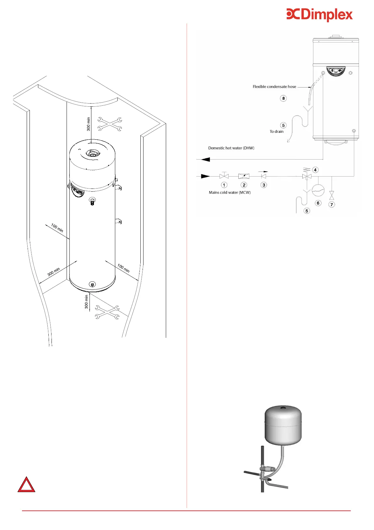
6.1 Correctly Siting the Water Heater
Install the water heater in an appropriate location, en-
suring all of the recommendations have been considered
(see Section 5.6 and 5.7).
6.2.1 Install the Inlet Group
The inlet group regulates the pressure of the incoming
mains water supply to the water heater and removes any
debris that might be water borne.
Between the inlet group and the cold
water inlet on the water heater NO isolating
safety devices could be isolated!
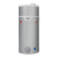
6.2.2 Expansion Vessel
The expansion vessel is mandatory on the Dimplex
water heater and can be connected directly to the cold water
-
-
ance with the manufacturer’s instructions, see Figure 5. No
and the cold water inlet group.
Furthermore, it is recommended to mount the vessel high-
er than the water heater to avoid having to drain the water
heater when maintaining and replacing the expansion vessel.
It is important to check the pre-charge pressure of the
pre-charge should be greater than or equal to 3 bar.
6.2 Cold Water Inlet with Inlet Group
Figure 4:Installationaccess
1.Stop valve*
2.Pressure-reducing valve
3.Check valve
4.Pressure relief valve
5.Drain*
6.Expansion vessel
7.Drainage valve
8.Condensates drainage*
* Components to be provided by the installer
Figure 5:Inletconnections
Figure 4 outlines the space requirements around the
appliance for ease of access, installation and maintenance
that must be adhered to.
Figure 6: Connection of expansion vessel