7
1-800-245-9917
Interconnections
All input, output and power connections are made at the bottom rear panel of the indicator. Refer to Figure No.
1 for the rear panel layout.
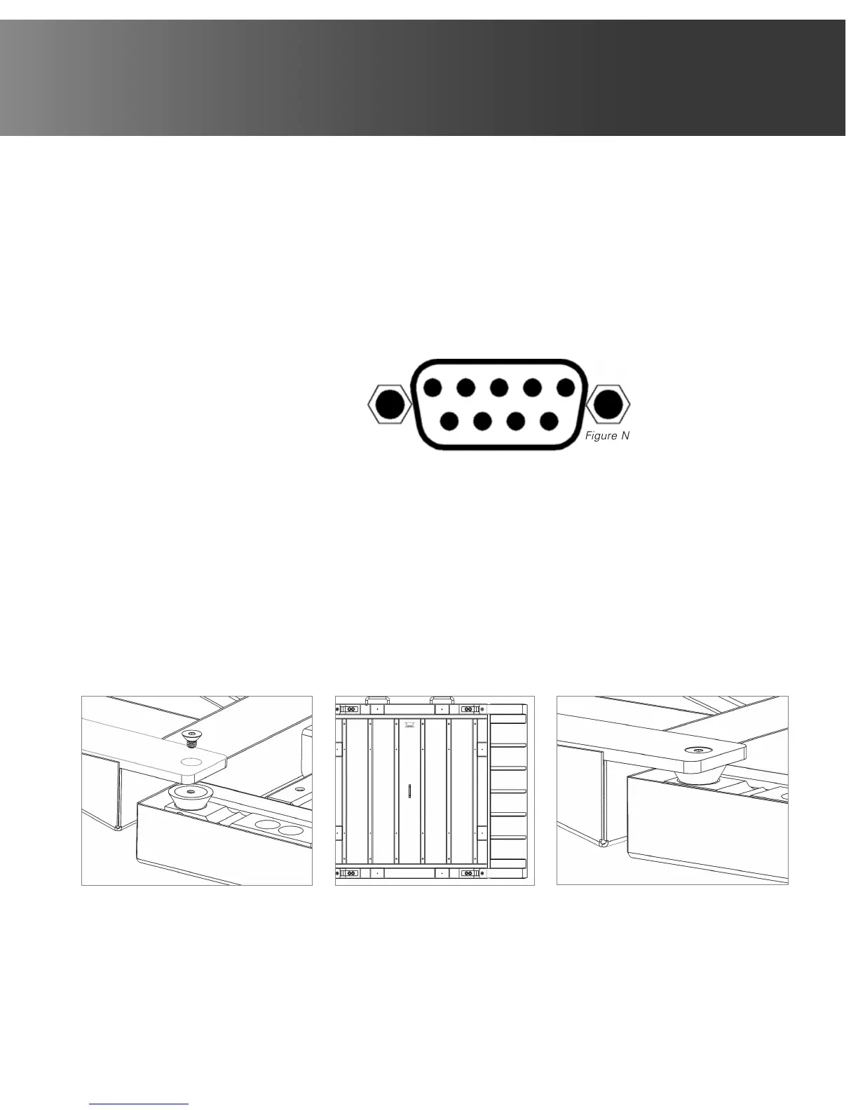
Load Cell Connection
The load cell cable connects to the Attendant Bluetooth Weight Indicator via a 9-pin “D” connector on the rear
panel of the indicator. Figure No. 4 shows the pin identification for the load cell connector. Make certain that
the pins are correctly identified before soldering a wire to them. Use the connector retaining screws to hold the
load cell cable connector securely to the rear panel.
PIN NO. FUNCTION
1 +EXCITATION
2 -SIGNAL
3 no connection
4 no connection
5 SHIELD
6 -EXCITATION
7 +SIGNAL
8 no connection
9 no connection
Assembly Steps for Attendant Wheelchair Scale Only:
NOTE: Assembly requires four screws and one Allen key (provided).
1. Fold and lock the column onto the scale platform. Lift the scale by its handles and place the platform on its
side in the storage position, supported by the metal stand.
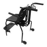
2. Attach each ramp in the following sequence:
- Begin by hand threading the screw into the top rubber mount while holding the ramp against the mount
(Figure No. 5).
- Hand thread the screw into the bottom rubber mount while holding the ramp against the mount.
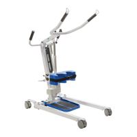
- Tighten both screws with the supplied Allen key (Figure No. 7).
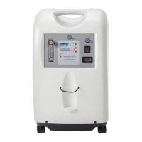
3. Repeat Step 2 for the ramp on the other side of the platform. Finished assembly should look like Figure No. 6.
Figure No. 4
12345
6789
Figure No. 5 Figure No. 6 Figure No. 7