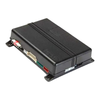
Platform: DBALL2
Firmware: CHRYSLER Remote Start Ready (RSR) Installation
© 2017 Directed. All rights reserved.
Rev.: 20170214
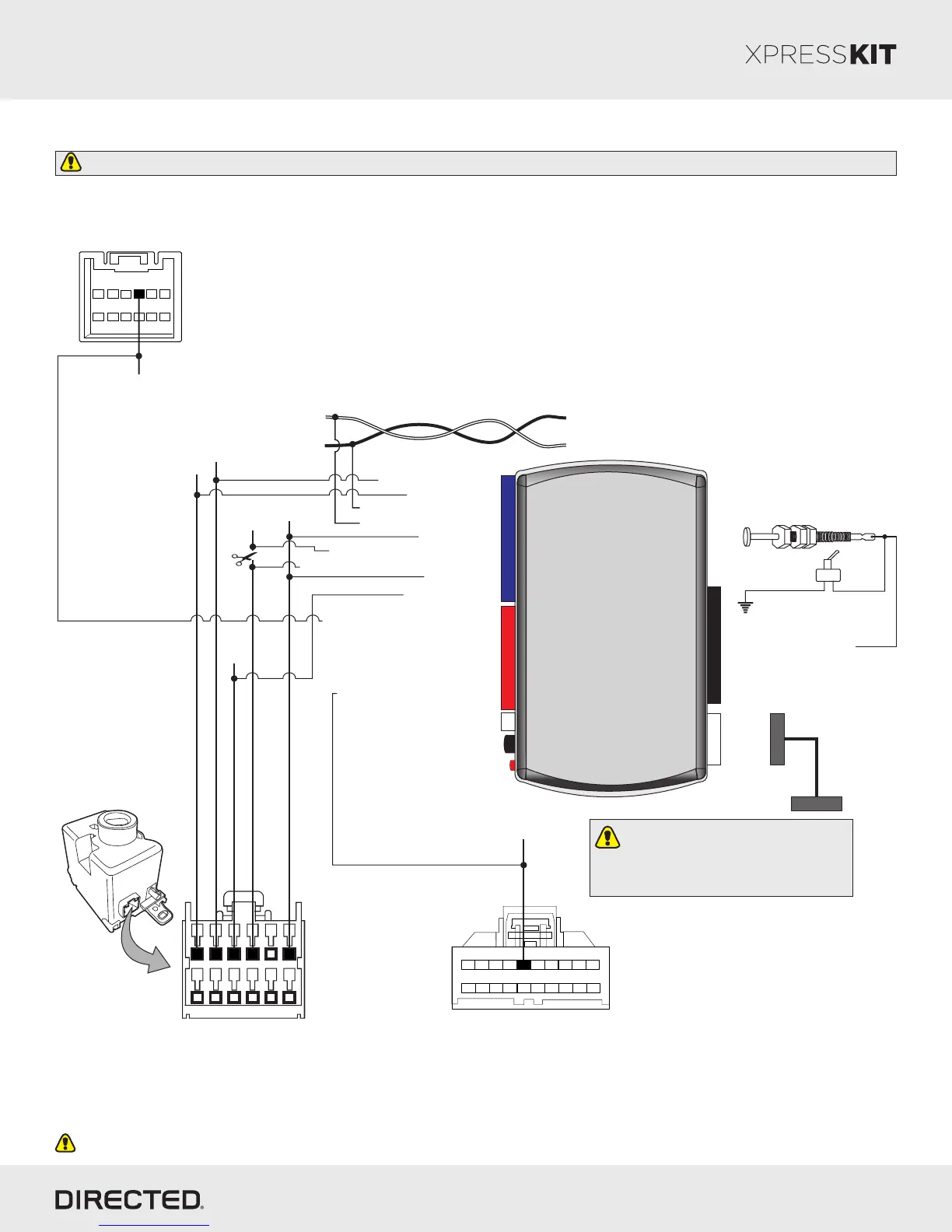
Ignition
Barrel
HS CAN High:White/Black or White/Lt. Green, pin 5
HS CAN Low: White/Lt. Blue, pin 6
1
6
12
7
(-) RAP Off Output: Yellow/Black: 10
(-) Parking Lights Output: Green/Black: 2
HS CAN High: Tan/Black: 3
HS CAN Low: Tan: 4
(+) 12V: Brown: 7
(-) Ground: Black: 14
(+) 12V: Red: 13
Twisted pair at the steering column or behind radio
White/Orange
White/Gray, White
White/Pink or White Black
Ignition Switch
(connector side view)
Ignition Interupt (vehicle side): Yellow: 8
Ignition Interrupt (conn.side): Orange/Yellow: 9
FT CAN High: Orange/Green: 5
FT CAN Low: Orange/Brown: 6
(+) Ignition: Pink/White, pin 3
(+) 12V:Lt.Blue/Red, pin 1
(-) Ground: Black/Striped, pin 4
20
11
1 10
5
Driver Door Module
(brown 20-pin conn.)
2 3 4 6 7 8
15
9
12
13
14
16 18 19
17
(-) Driver Door
Trigger: Violet, pin 5
Hazard light switch
(black 12-pin conn.)
1
2
3
4
5
6
7
8
9
10
11
12
(-) Hazard Lights:
White/Dk.Blue,
pin 4
Refer to the Vehicle Wiring Reference Charts for wire color and location.
CUT
Installation Type 4 - without T-Harness
Page 13
10
DBALL2
Prog. Button
LED
4
14 12 2
RF
TX
(-) Ground
RX
(+) 12V
6: White/Black: (-) Hood Input
Hood Pin
Remote Start Safety
Override Switch
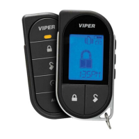
You can connect to either a XL202
RFTD OR a SmartStart module.
Refer to the SmartStart/XL202
Installation Notes for more information.
All connectors are displayed from the wire side (unless specified otherwise).