36
DS4+ FORD6
© 2017-12-13 Directed. All rights reserved.
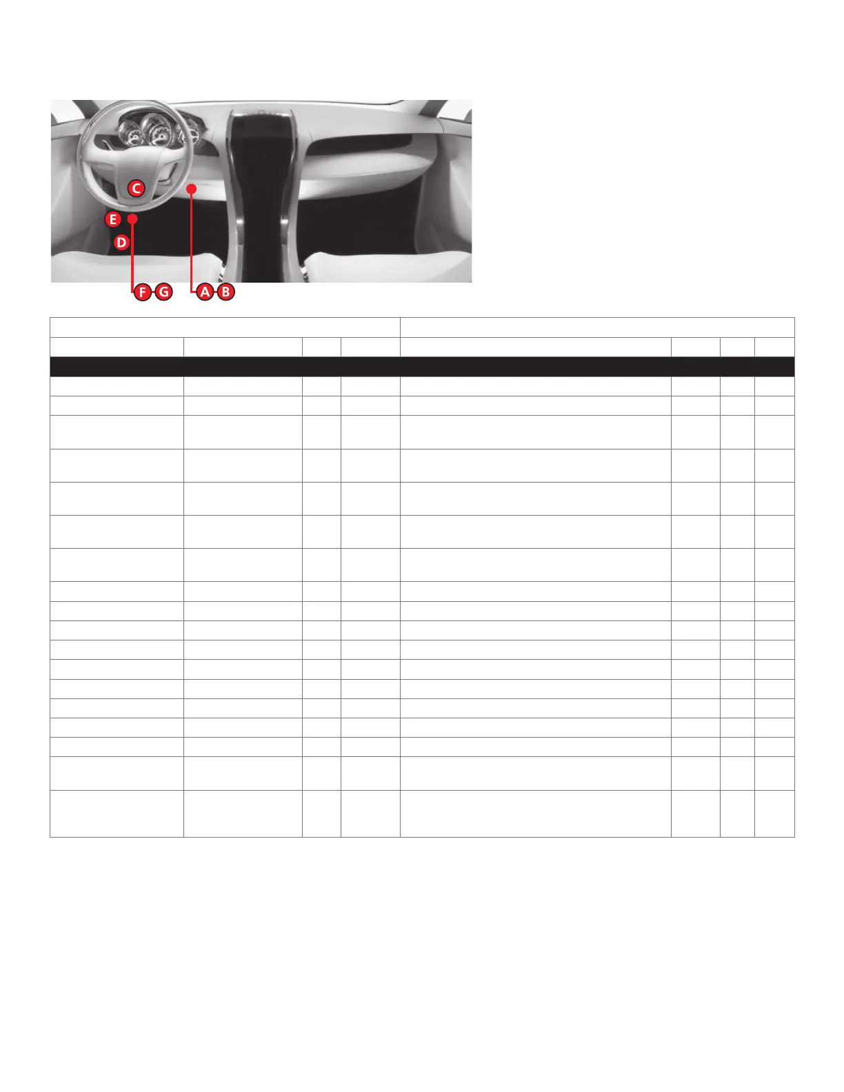
Vehicle wiring reference chart
This section provides vehicle wiring information to guide you through the various stages of your installation. Refer to
www.directechs.com for additional information.
Wire Information Connector Information
Function Color Pin Polarity Location Color Pins Ref.
Ford E-Series 2008
RX Gray/Orange 3 Data (PATS) connector. N/A 4 A
TX White/Lt. Green 4 Data (PATS) connector. N/A 4 A
12V Lt. Green/Violet 2 (+) Ignition switch. Gray or
Black
13 B
Starter White/Pink 5 (+) Ignition switch. Gray or
Black
13 B
Ignition Pink/Lt. Green 1 (+) Ignition switch. Gray or
Black
13 B
Accessory 1 Gray/Yellow 8 (+) Ignition switch. Gray or
Black
13 B
Accessory 2 Black/Lt. Green 3 (+) Ignition switch. Gray or
Black
13 B
HS CAN High White/Lt. Green 6 Data OBDII. Black 16 C
HS CAN Low Pink/Lt. Green 14 Data OBDII. Black 16 C
MS CAN High White/Black 3 Data OBDII. Black 16 C
MS CAN Low Black/Yellow 11 Data OBDII. Black 16 C
Parking Lights Brown N/A (+) Drivers kick panel harness to rear. N/A N/A D
Driver Door Trigger Red/Pink N/A (-) Drivers kick panel. N/A N/A E
Lock (with keyless entry) Orange/Black or Red N/A (-) Drivers kick panel door harness. N/A N/A E
Unlock (with keyless entry) Yellow/Red or Brown N/A (-) Drivers kick panel door harness. N/A N/A E
Lock (without keyless entry) Pink/Yellow N/A 5-wire Drivers kick panel door harness. N/A N/A E
Unlock (without keyless
entry)
Pink/Lt. Green N/A 5-wire Drivers kick panel door harness. N/A N/A E
Tach White/Pink N/A (AC) "Customer Access Harness is around the middle of the
main harness that runs along the top of the firewall,
under the hood."
N/A N/A N/A
 Loading...