7
933.TL14 1.02.198.9 2023 Toyota Camry
©2023 VOXX•DEI LLC. All rights reserved.
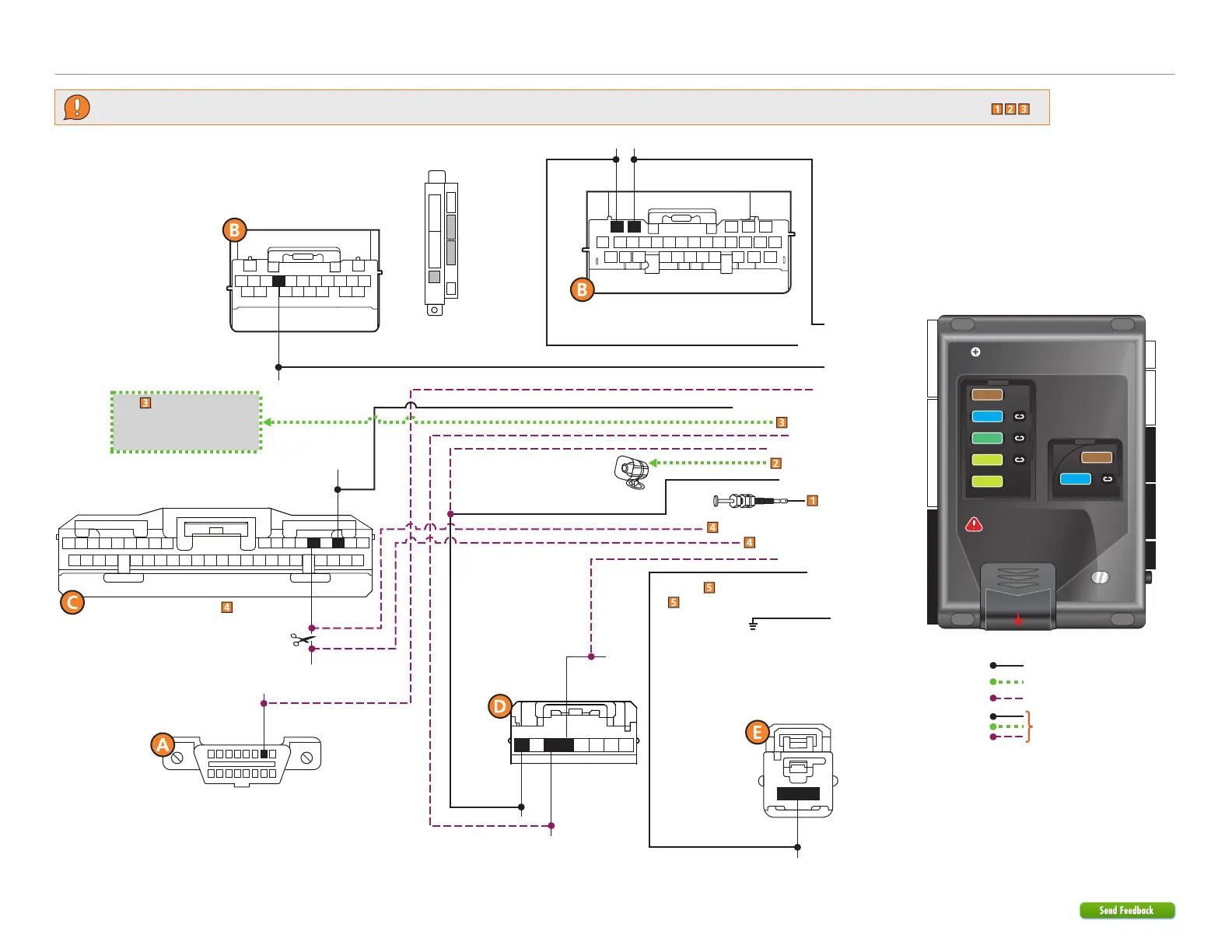
Refer to "Pre-installation and application warnings" for important information, such as the description of each special note referenced in the diagram ( ).
16
8
9
1
Wiring diagram
OBDII Diagnostic Connector
HS CAN Low:
White, pin 4
HS CAN High:
Tan, pin 5
SIL Data:
Blue, pin 7
(+) Ignition Output: Violet/Black: 8
(+) Ignition Sense Input: Pink: 12
(+) Accessory Output: White: 7
(-) Hood Input: Gray: 21
(+) Siren Output: Brown/Red: 11
Siren
Hood Pin
(+) 12V Input: Red: 6 & 12
HS CAN Low 1: Tan: 1
HS CAN High 1: Tan/Black: 2
RDA: Orange/Black: 7
SIL Data: Yellow/Black: 8
(-) Ground: Black: 10
RDA: Red,
pin 10
1
Dash Fuse Box
(white conn.)
(+) 12V:
White, pin 1
Cut
(-) Parking Light Output: Lt. Green/Black: 1
Body ECU
Connector
Body ECU Connector
(lower conn. left side
of steering column)
12345678
Ignition
Connector
123456781112131415161718
9
10
313233343536
3738
30
2122
232425262728
20 19
29
3940
Headlight Switch
Body ECU
(middle conn. left side of steering column)
678
111213
1415161718
9
10
21 20 19
12
3
45
678
1112131415161718
9
10
30
2122
232425262728
20
19
29
1
2345
(+) Ignition:
Lavender/Red,
pin 8
(+) Accessory:
Lt. Green, pin 6
(+) Starter:
Lavender/Violet,
pin 5
2
2
Autolight Interrupt (conn. side): Blue/White: 1
Autolight Interrupt (veh. side): Blue: 3
Autolight: White
or Yellow, pin 5
(-) Parking Light: Blue/Black
or Green, pin 3
(+) Starter Output: White: 5 & 11
TPMS Ignition Interrupt (veh. side): Lt. Green: 8
TPMS Ignition Interrupt (conn. side): Lt. Green/White: 9
(-) GWA Output: Blue/White: 2
Refer to the
Starter disable connection
section for relay and
connector details.
Security Only
Mandatory Connections
Remote Start Only
Legend:
Remote Start + Security
22 812
4 2442
Slide to open
A module can also be used for
this installation.
IMPORTANT:
Position the
fuses correctly!
MAIN (5A) (+)
(-) RLY3 PK LIGHT (15A) (+)
(-) ACC & START (30A) (+)
(-) FLEX RLY (20A) (+)
IGN (20A) (+)
MAIN (5A) (+)
(-) RLY3/PK LIGHT(15A) (+)
5
5
30
20
20
15
15
1
1
3
3