6
933.TL14 1.02.198.9 2023 Toyota Camry
©2023 VOXX•DEI LLC. All rights reserved.
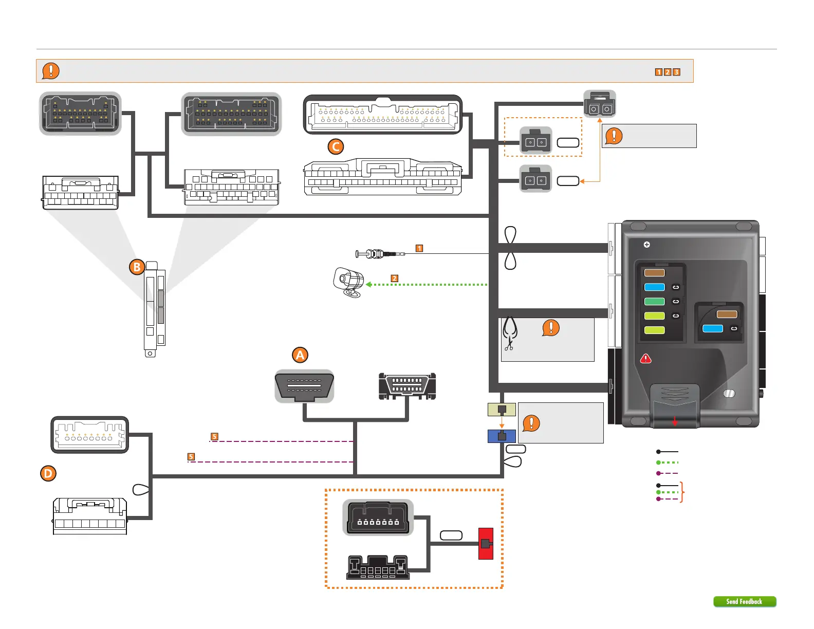
Refer to "Pre-installation and application warnings" for important information, such as the description of each special note referenced in the diagram ( ).
Siren
Hood Pin
(-) Hood Input: Gray
(+) Siren Output: Brown/Red
THTON7
(optional T-Harness)
Wiring diagram with T-Harness (THTON7)
12-pin Black Connector
Body ECU
Connector
1
2
8-pin White Connector
22-pin White Connector
Headlight Switch
Body ECU Connector
(lower conn. left side
of steering column)
Body ECU
(middle conn.
left side of steering column)
1
2
NOT USED
A
B
Diagnostic Connector OBDII
Ignition Connector
NOT USED
C
B
TPMS Ignition Interrupt (veh. side): Lt. Green
TPMS Ignition Interrupt (conn. side): Lt. Green/White
Connect the connector
labeled Type A.
Connect the Tan
12-pin connector to
the 12-pin Blue
connector labeled B.
Cut the Dk.Green/Black
and Dk. Blue/Black loop
labeled Lock/Unlock.
Security Only
Mandatory Connections
Remote Start Only
Legend:
Remote Start + Security
22 812
4 2442
Slide to open
A module can also be used for
this installation.
IMPORTANT:
Position the
fuses correctly!
MAIN (5A) (+)
(-) RLY3 PK LIGHT (15A) (+)
(-) ACC & START (30A) (+)
(-) FLEX RLY (20A) (+)
IGN (20A) (+)
MAIN (5A) (+)
(-) RLY3/PK LIGHT(15A) (+)
5
5
30
20
20
15
15