10
933.HONDA9 2.10.198.12 2018 Honda Civic (Smart Key)
©2023 Directed. All rights
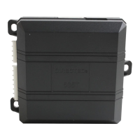
Locating components in the vehicle
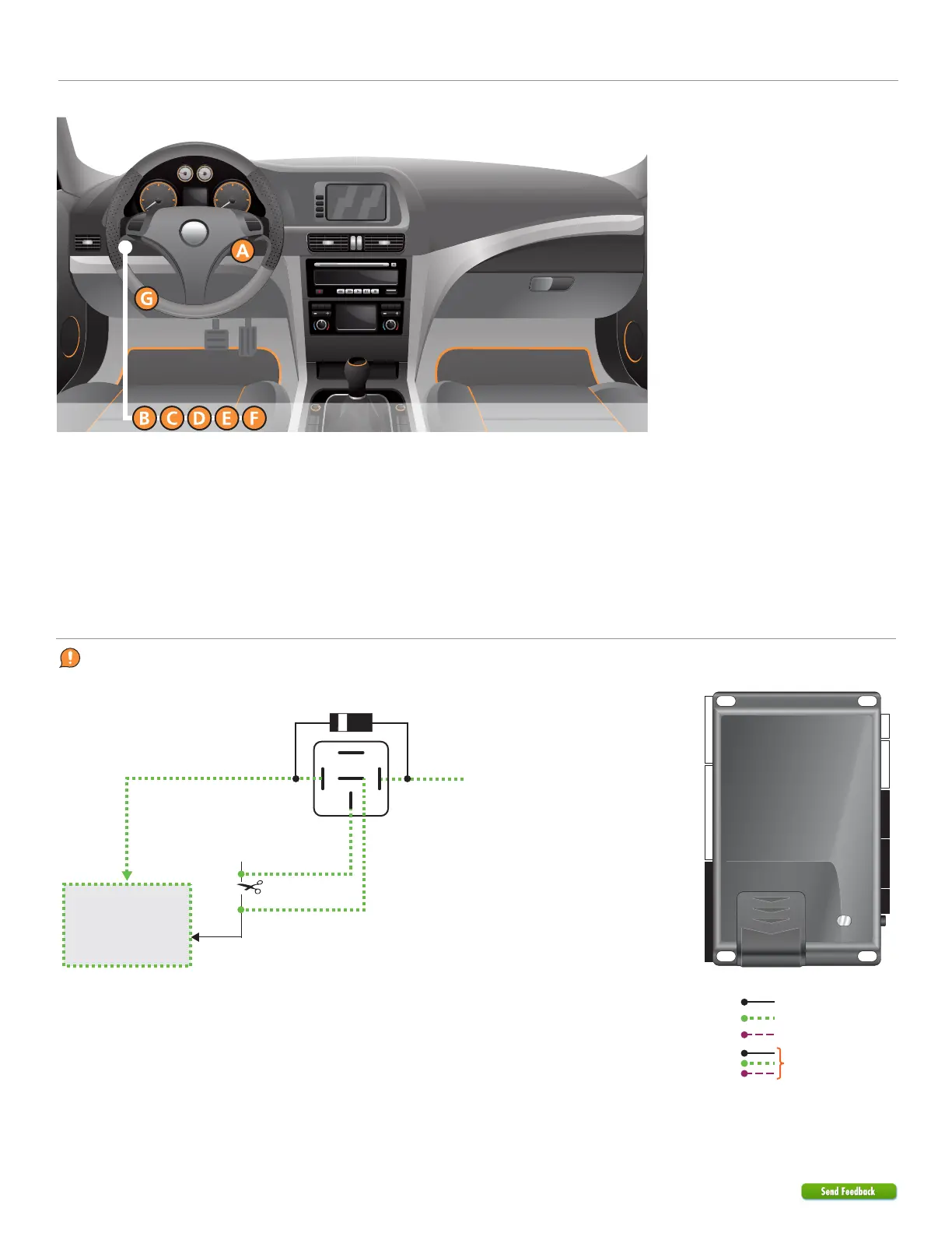
86 85
30
87a
87
Refer to the
Vehicle connections
section for wire
and connector
details.
(-) Ground When Armed (GWA) Output: Red/White: 4
Starter (vehicle side)
Starter (connector side)
(+) Ignition
Ignition
(vehicle side)
Cut
Security Only
Mandatory Connections
Remote Start Only
Legend:
Remote Start + Security
Optional starter disable connection
1A Diode (1N4002+)
When using an external relay, use a 1N4002 diode or larger.