7
933.HONDA9 2.10.198.12 2018 Honda Civic (Smart Key)
©2023 Directed. All rights
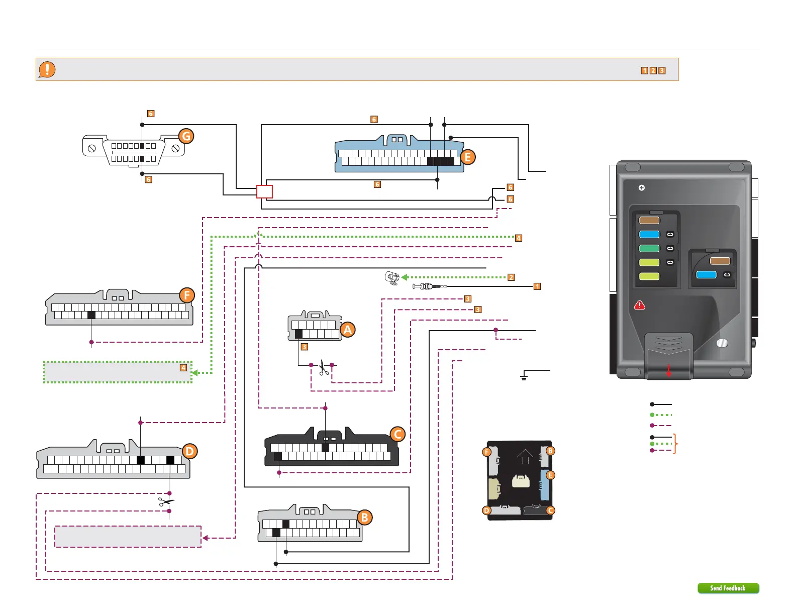
Refer to "Pre-installation and application warnings" for important information, such as the description of each special note referenced in the diagram ( ).
26
BCM
(gray connector)
9
32
35
119
40
20
20
21
22
23
Wiring diagram with Vehicle Takeover
(+) 12V:
Red, pin 27
11
27
(-) Parking Lights: White or Gray, pin 11
Immo. Data:
Yellow or Red, pin 35
B-CAN High: Pink, pin 20
B-CAN Low: Blue or Tan , pin 21
(-) PTS:
Blue or Black, pin 9
(+) Accessory: Gray, pin 32
Immobilizer Data: Yellow/Black: 8
(-) Parking Lights Output: Lt. Blue/Black: 10
(-) Push-To-Start Output: Lt. Green/Black: 1
(+) Starter Output: Violet/Black: 8
(+) 12V Input: Lt. Green/Red: 7
(+) Accessory Output: White: 5 &11
(+) 12V Input: Red: 6 &12
(-) Ground: Black: 10
Steering Lock Module
(gray connector
under steering column)
Ignition Interrupt 1 (veh. side): Lt. Green: 8
Ignition Interrupt 1 (conn. side): Lt. Green/White: 9
Ignition Interrupt 1: Pink or White, pin 2
(-) Takeover Output: Dk.Blue/Black: 9
(+) Starter: Yellow
or Lt. Blue, pin 6
Cut
12
Siren
Hood Pin
(-) Hood Input: Gray: 21
(+) Siren Output: Brown/Red: 11
Ignition Interrupt 2 (vehicle side): Blue/White: 1
Ignition Interrupt 2 (connector side): Blue: 3
Cut
Refer to the Starter disable connection
section for relay and connection details.
(-) GWA Output: Red/White: 4
HS CAN Low 2: Tan: 1
HS CAN High 2: Tan/Black: 2
HS CAN High 1: Orange/Green: 4
HS CAN Low 1: Orange/Brown: 3
F-CAN Low: Pin 23
Refer to the next page for the mandatory
Vehicle Takeover connections.
BCM connectors
(behind or above dash fuse box)
BCM
(gray connector)
BCM
(gray connector)
BCM
(blue connector)
BCM
(black connector)
1
118
36 19
1
116
17
14
28
15
19
36
18
Security Only
Mandatory Connections
Remote Start Only
Legend:
Remote Start + Security
22 812
4 2442
Slide to open
A module can also be used for
this installation.
IMPORTANT:
Position the
fuses correctly!
MAIN (5A) (+)
(-) RLY3 PK LIGHT (15A) (+)
(-) ACC & START (30A) (+)
(-) FLEX RLY (20A) (+)
IGN (20A) (+)
MAIN (5A) (+)
(-) RLY3/PK LIGHT (15A) (+)
5
5
30
20
20
15
15
OBDII
Diagnostic
Connector
16
8
9
1
OR
Ignition Interrupt 2:
Blue, pin 12
F-CAN High: Pin 22
DIAG CAN High:
Green or White, pin 6
DIAG CAN Low:
Red or Tan, pin 14