6
933.HONDA9 2.10.198.12 2018 Honda Civic (Smart Key)
©2023 Directed. All rights
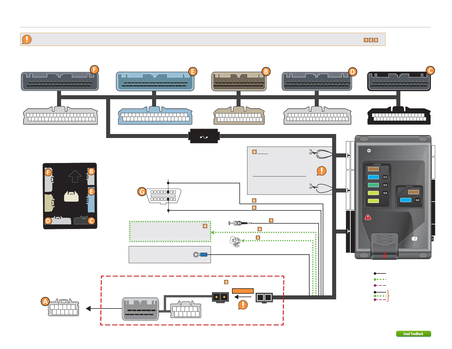
Refer to "Pre-installation and application warnings" for important information, such as the description of each special note referenced in the diagram ( ).
Before installing the t-harness:
Cut the Orange/Brown &
Orange/Green loops ONLY if
connecting HS CAN 1 at the
OBDll Diagnostic.
Cut the Brown/Black loop to
disable the Horn Output.
Connect ground terminal to
existing vehicle 10 mm bolt.
(-) GWA Output: Red/White
Refer to the
Optional starter disable connection
section for relay and connection details.
Hood Pin
Siren
HS CAN 1 Low: Orange/Brown
HS CAN 1 High: Orange/Green
16
8
9
1
DIAG CAN High: White or Green, pin 6
DIAG CAN Low: Red or Tan, pin 14
OBDII Diagnostic
(connector side view)
(-) Ground: Black
Wiring diagram with T-Harness (THHON7) with Vehicle Takeover
THHON7
(optional t-harness)
BCM Connectors
(behind or above dash fuse box)
Gray
connector
Blue
connector
Gray
connector
Black
connector
Gray
connector
Steering Lock Module
(gray connector
under steering column)
2-pin
black connector
2-pin
black connector
Relay Pack
5A Fuse Inside
BCM
(40-pin gray connector)
BCM
(36-pin blue connector)
BCM
(28-pin gray connector)
BCM
(36-pin gray connector)
BCM
(32-pin black connector)
Security Only
Mandatory Connections
Remote Start Only
Legend:
Remote Start + Security
22 812
4 2442
Slide to open
A module can also be used for
this installation.
IMPORTANT:
Position the
fuses correctly!
MAIN (5A) (+)
(-) RLY3 PK LIGHT (15A) (+)
(-) ACC & START (30A) (+)
(-) FLEX RLY (20A) (+)
IGN (20A) (+)
MAIN (5A) (+)
(-) RLY3/PK LIGHT (15A) (+)
5
5
30
20
20
15
15
(-) Hood Input: Gray
(+) Siren Output: Brown/Red
Connect
Steering Lock