17
IP2160EN
Before connecting the power supply, make sure the plate data correspond to that of the
mains power supply.
An omnipolar disconnection switch with a contact opening distance of at least 3mm must
be fitted on the mains supply.
Check there is an adequate residual current circuit breaker and overcurrent cutout upstream
of the electrical system.
For the power supply, use a H05RN-F 3G1.5 type electric cable. Connect it to terminals L (brown),
N (blue), (yellow/green) inside the automation.
NOTE: the maximum permisible section of the wire is AWG14 (2 mm
2
).
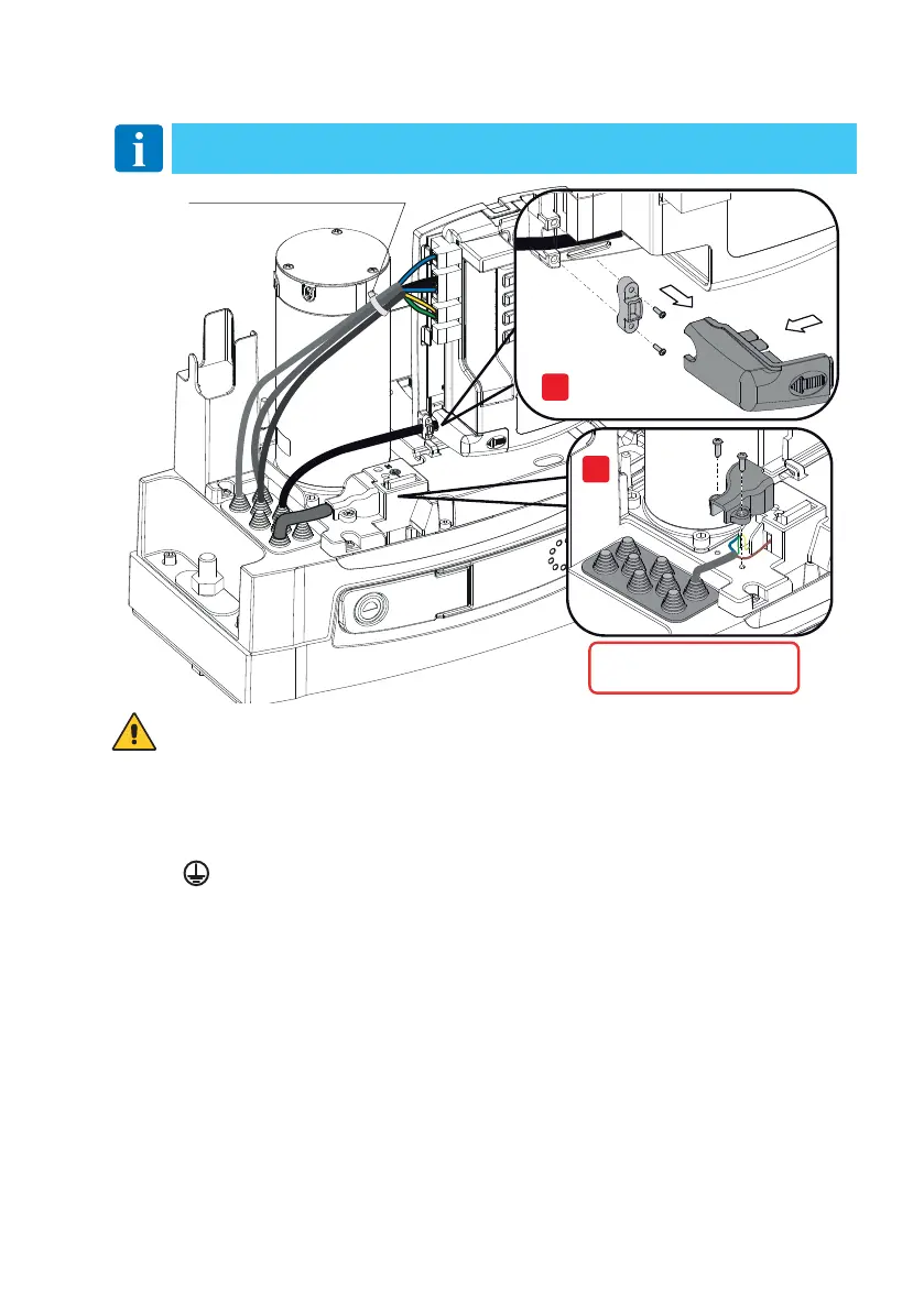
Unsheathe the power supply cable in line with the terminal, and use a cable fastener to hold it
in place (see ref. B).
In order to comply with essential requirements of standards in force, reclose the cover once
the wires have been connected to the terminal.
In the external automation section, the connections to the mains power supply and any other low
voltage wires (230V) must be made on an independent channel separated from the connections
to the command and safety devices (SELV = Safety Extra Low Voltage).
The channel must penetrate the automation through the holes on the base plate by a few cen-
timetres.
Make sure there are no sharp edges that may damage the power supply cable.
Make sure the mains power wires (230V) and the accessory wires (24V) are separated. The cables
must be double insulated. Unsheathe them in line with the relative connection terminals, and
use cable fasteners (see ref. A) or straps (not supplied by us) to hold them in place.
6. Electrical connections
Assicurarsi che il conduttore
giallo verde sia almeno 30 mm
più lungo dei conduttori marrone e blu
L
N
A
B
Fascetta non di nostra fornitura
NOTE: the electrical wiring and start-up of the gearmotors is shown in the CS12E and
CS12M control panel installation manuals.
Make sure that the yellow-green
conductor is at least 30 mm longer
than the brown and blue conductors
Tie not supplied

 Loading...


