7
IP1854EN - 2013-03-01
Output Value - Accessories Description
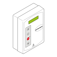
Membrane push-button panel (PT3).
Starts the opening operation.
Note: to activate the closing operation, connect the connector of the push-button panel to J7
(rotated by 180°).
Membrane push-button panel (PT3).
Causes the blocking of the movement.
Membrane push-button panel (PT3).
Starts the closing operation.
Note: to activate the opening operation, connect the connector of the push-button panel to J7
(rotated by 180°).
6. Adjustments
6.1 Trimmer
6.2 Dip-switch
Trimmer Description
TM
MIN=10 s MAX=120 s
Setting the operating time. From 10 to 120 s.
NOTE: with NC limit switch, set TM=MAX.
TR
MIN=0 s
20 s
30 s
3 s
Setting motor 1 (M1) closing delay time.
When closing, motor 1 (M1) starts after a delay set with TR from 0 to 30 s relative to M2. When opening, motor 2
(M2) starts after a delay of 3 s relative to M1.
If TR=MIN, the door wings start simultaneously.
NOTE: we recommend setting TR=MIN with non-overlapping door wings, and setting TR>3 s with overlapping door
wings.
TC
Setting automatic closing time. From 0 to 120 s.
With DIP3=OFF, once a safety switch has been activated, the counter starts as soon as the safety switch is released
(for example, after passing through the photocells), and lasts for a period of time set with TC (50%).
With DIP3=ON, the counter starts when automation is opened and lasts for the entire duration set with TC (100%).
NOTE: after the activation of the stop command, once contact 1-9 has closed again, automatic closing is only ena-
bled after a total, partial or step-by-step opening command.
RF
5
4
3
2
Power setting.
Sets voltage supplied to motor (1=MIN / 5=MAX).
R1
MAX=disabled
MIN
Setting obstacle thrust.
The control panel is equipped with a safety system that stops motion if an obstacle is encountered during an opening
operation and either stops or reverses motion during a closing operation.
R1=MIN gives maximum obstacle sensitivity (minimum thrust).
R1=MAX disables detection (maximum thrust).
RP
Setting motor 1 (M1) partial aperture.
From 0 to 30 s.
DIP Description OFF
ON
DIP1 Radio mode. Step-by-Step. Opening.
DIP2 Direction selection with OM=OFF (one mo-
tor mode).
Opens towards right. Opens towards left.
DIP3 Restore automatic closing time. 50% 100%
DIP4 Automation status at power on.
Indicates how the control panel considers
automation when powered up.
Open.
NOTE: with a limit switch installed, prefera-
bly set DIP4=OFF.
Closed.
NOTE: if the automatic closing function is
not used, preferably set DIP4=ON.
DIP5 Electric lock release. Disabled. Enabled.
DIP6 Preflashing set at 3 s. Disabled during opening.
Enabled only with automatic closing and
with TC setting greater than 3 s.
Enabled for both opening and closing.
Intelligent Security & Fire Ltd.