IC100C Series PRELIMINARY
1592015000 Manual IC100C Series 28/05/03 Page 12 di 38
26. RELAY CONFIGURATION
Relay n° 1 = Compressor 1
Relay n° 2-3 automatically change their configuration
depending on the unit configuration.
Relay n° 2 = Anti-freeze heater CF01 = 2-3-4-5; integration
heater with CF01 = 0 - 1
Relay n° 3 = Water pump, with CF01 = 2-3-4-5; supply air
fan CF01 = 0 –1
Value of par.CF20
Relay
0 1
°n 4
Inversing
valve
Fan ON/OFF
Value of par.CF21
Relay
0 1 2 3
°n 5 Alarm
Stage of the 1
st
compressor.
2
nd
compre
ssor
Fan
ON/OFF
When working with one compressor with one stage valve:
the relay n°5 is configured as stage valve CF21=1: the
polarity of the stage valve is determined by C010.
CO10 = 0 RL1 comp. RL5 parz.
No call OFF OFF
Compressor call ON OFF
1
st
Stage call ON ON
CO10 = 1 RL1 comp. RL5 parz.
No call OFF ON
Compressor call ON ON
1
st
Stage call ON OFF
27. DATA LOGGER
The data recording is enabled if the log time LG08 > 0.
The recordable data can be included enabling the LG01 to
LG07 parameters.
28. BOILER FUNCTION
The electric heater can be activated as heating integration
control Ar20=0 or heating control Ar20=1 during the heat
pump functioning mode.
It is enabled only if:
• Unit configured in Heat Pump mode CF01=3-5.
• Pb4 configured as external air probe CF07=3.
28.1 Heating Integration Control Ar20=0
The Boiler function starts when the Pb4 probe value
decreases under Ar21 value.
If the water temperature detected by the regulation probe is
lower than the ST03 parameter, the electric resistance
heater is activated. The on/off algorithm of the electric
resistance heater is the same as the compressor control
with Heat Pump mode.
If the external air temperature becomes higher than Ar21 +
Ar22 (differential), the integration function stops working
and the unit restarts (or still work) with Heat Pump mode.
28.2 Heating Control Ar20=1
The Boiler function begins when the Pb4 probe decreases
under Ar21 value. When the delay is expired, if the water
temperature detected by the regulation probe is lower than
the ST03 parameter, the compressors are stopped while
the electric resistance heater is activated. The on/off
algorithm of the electric resistance heater is the same as
the compressor control with Heat Pump mode.
If the external air temperature becomes higher than Ar21 +
Ar22 (differential), the Boiler functions stops working and
the unit restarts with Heat Pump mode, compressors and
fans restart working.
29. MAINTENANCE FUNCTION
CO14 for 1
st
compressor, CO15 for 2
nd
compressor and
CO16 for water pump or supplied air fan (air/air) are the
maximum time running hours to signal a maintenance
request, the icon
is blinking. The icon only indicates
the need of a check: nothing else happens. It stops
blinking just after resetting the hour counter under the
function Menu.
30. BLACK OUT
After a black-out:
1. The controller restarts from the pervious status.
2. The defrost cycle is stopped.
3. All the working time delay will be reloaded.
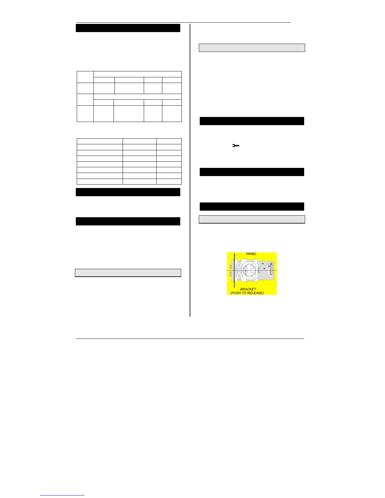
31. INSTALLING AND MOUNTING
31.1 “C” Format (32*74mm)
The instrument shall be mounted on panel, in a 29x71 mm
hole, and fixed using the special bracket supplied.
To obtain an IP65 protection grade use the front panel
rubber gasket (mod. RG-C) as shown in figure 1.
 Loading...