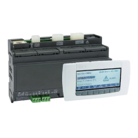
IC100C Series PRELIMINARY
1592015000 Manual IC100C Series 28/05/03 Page 8 di 38
4. If the password is active enter its value.
5. The infrared icon
is now lighted. The controller
starts sending the data. You have 1 minute to place
the IR receiver device in front of the instrument.
6. On the receiver, push RX key to enable the
receiving: the RX led blinks during the interlacing
procedure. During the data transferring the RX is
lighted, it turns off to signal the end of the procedure.
7. To exit the function menu push and release the M
key or wait the time-out. The “menu” icon disappears.
16.9 How to See the Alarm Log
1. Enter the function Menu.
2. Use o or n keys to find ALOG label.
3. Push SET key: the lower display shows the alarm
code, the upper display shows “n°” followed by the
progressive number.
4. With o or n scroll the alarm list.
5. To exit from ALOG function push M key or wait the
time-out delay is expired.
The memory contains 50 alarm events structured in a FIFO
list. Each new alarm will take the place of the oldest alarm
contained in the FIFO list. ( the read-out is ordered from the
oldest to the newest)
16.10 How to Reset the Alarm Log
1) Enter the function Menu.
2) Select the ALOG label showed on the lower display.
3) Push SET key.
4) Select with o or n keys the ArSt (Alarm reset) label
on the lower display, the upper display is PAS.
5) Push SET key and then enter the password PAS,
upper display shows 0 blinking.
6) Write the right password number.
7) The ArSt label starts blinking for 5s, to confirm the
alarm logging data is reset.
After finishing the display restarts from normal condition.
17. KEYBOARD FUNCTIONS
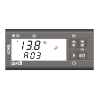
17.1 How to See the Set Point Value
Push and release the SET key.
Lower display shows: SetC set of chiller mode;
SetH set of heat pump mode.
The upper display shows the corresponding set value.
(SetH is available only if configured for Heat Pump).
17.2 How to Change the Set Point Value
1) Push SET key for more than 3 seconds.
2) The setpoint value is now blinking.
3) Use o and n
to increase or decrease the new value.
When finishing, push and release SET key again or wait for
the time-out to exit the programming.
17.3 How to See the Set Point with Energy
Saving or Dynamic Set Functions Enabled
When working in Chiller or Heat Pump, the first time SET
key is pushed the lower display shows SEtC (set chiller); or
SEtH (set heat pump) and the upper shows its value.
When the “Energy Saving” is activated, by pressing SET
key again, the lower display shows “SEtS” (set saving)
while the upper display will turn to the real setpoint value
used to control the unit during this function.
When working with “Dynamic Set”, by pushing SET again,
the lower display shows “SEtd” (set dynamic), while the
upper display will turn to the real setpoint value used to
control the unit during this function.
The SEtS or SETd appears only if the corresponding
functions are activated.
18. HOW TO TURN A COMPRESSR IN OFF-LINE
A compressor can be turned off for maintenance or if it is in
bad condition, without interfering with the normal cycle of
the unit. Therefore, it is not necessary to stop the unit or the
cycle.
1. Access the programming mode.
2. Find and then set the parameter CO12 = 1
(compressor 1 = OFF: out of the process control).
3. If necessary find and then set also the parameter
CO13 = 1 (2
nd
comp. / step 1
st
comp.= OFF).
To restore the compressor in the process control set the
C012 and/or C013 parameter = 0.
19. DYNAMIC SET POINT
This function is useful to save energy or to run the unit with
particular external air temperature condition. It allows to
increase or reduce the setpoint with a positive or negative
proportional offset. This value is combined with parameters
Sd02 (for Chiller) or Sd03 (for HP), the 4...20mA analogue
input or the outside air temperature.
The Dynamic Set is enabled if:
- The parameters Sd01 = 1 and CF06 = 3, Pb3 probe
configured as 4..20mA signal;
- The parameter Sd01 = 1 and CF07 = 3, Pb4 probe
configured as outside air temperature. If the parameter
CF07=3, by pushing and releasing the n key the upper
display shows for 30 seconds the outside air temperature
while the lower display shows Et (external temperature)
label.
Pb3 probe configured as 4..20mA input signal (below)
 Loading...