7
INSTALLATION
All “left”, “right”, “front” and “rear” desig-
nations in this manual are as viewed by the
operator facing the control console.
LOCATION
1. The oor area required by the standard machine
is 105.25 inches (2673.4 mm) in width by 60.18
inches (1528.6 mm) in length. Machine height is
78.81 inches (2001.8 mm). Refer to pages 1, 2
and 3 for further machine dimensions.
2. The machine’s nal location should also provide
the following:
• Sufcient space for easy stock loading and re-
moval.
• Adequate clearance for necessary door openings,
lubrication, maintenance and repair procedures,
including optional chip conveyor removal.
3. Accessories such as conveyors or material handling
equipment will require additional work area.
OSHA NOTICE!!
OSHA Regulation 1910.212 (5B).
Machinesdesignedforaxedlocationshall
be securely anchored to prevent walking or
moving.
UNPACKING
1. The machine is fastened to and shipped on a wooden
skid. Overseas shipments are also crated.
2. Place the machine in its nal position and remove
all protective covers, strapping, crating, etc. Then:
(a) DO NOT remove the bracket which fasten the
saw head to the saw frame; (b) Remove all bolts
which fasten the machine to the shipping skid; (c)
Check around the machine for boxes and/or other
extra machine parts which may have been placed
there for shipment; (d) Inspect the machine and all
parts for shipping damage. Claim procedures are
listed on this manual’s inside front cover.
LIFTING
NEVER lift the machine by its sawing head.
1. Four (4) permanent lifting lugs are provided for
machine lifting purposes and are located in each
corner of the machine base.
2. Using chains attached to the lifting lugs, it is recom-
mended that lifting and transporting the machine be
done with an overhead hoist. It may be necessary to
protect the saw's surfaces from damage where the
chains come in contact with such areas. Net weight
is approximately 3800 pounds (1723.7 kg).
3. Conveyors or material handling equipment can be
lifted and transported by overhead hoist, fork lift,
or by other means that provides adequate safety
precautions.
FLOOR INSTALLATION
1. Thread the seven (7) provided leveling screws
(M20 x 2.0) into the machine base mounting holes
and attach the jam nuts. Position the foot castings
under the leveling screws.
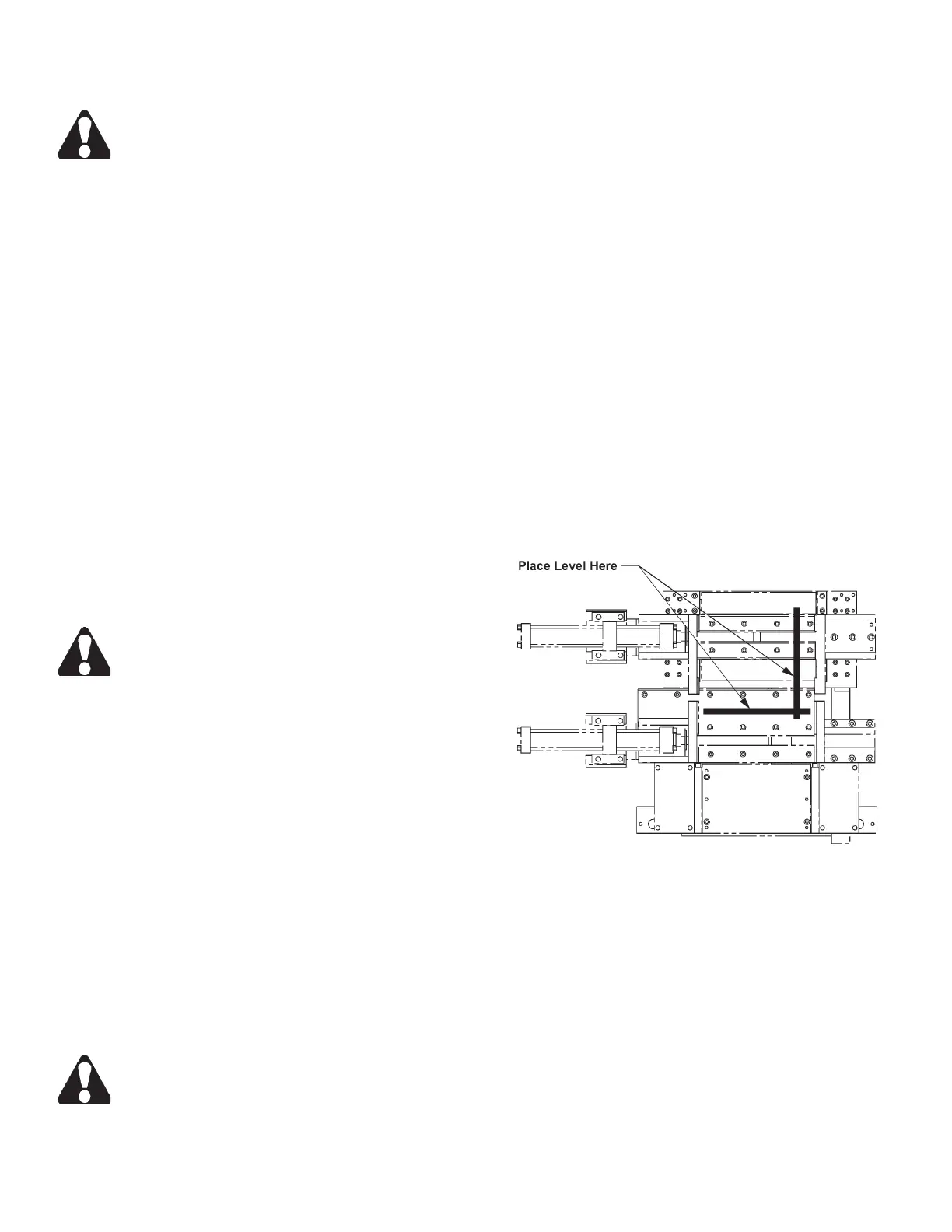
2. Place a machinist’s level on the outboard vise bed
and inboard rollers of the index vise. Adjust the
leveling screws until the machine is level and weight
bears evenly on all mounting pads.
Leveling the Machine.
3. The following are important dimensions to be ob-
tained during leveling:
• The roller and vise bed bearing surfaces are to be
co-planar within 0.015 inch (0.38 mm).
4. After the machine has been leveled, install anchor-
ing screws through the base pad holes next to the
leveling screws.
5. Remove the protective shipping bracket installed
to connect the saw head to the base frame during
shipping.