11
MACHINE CONTROLS
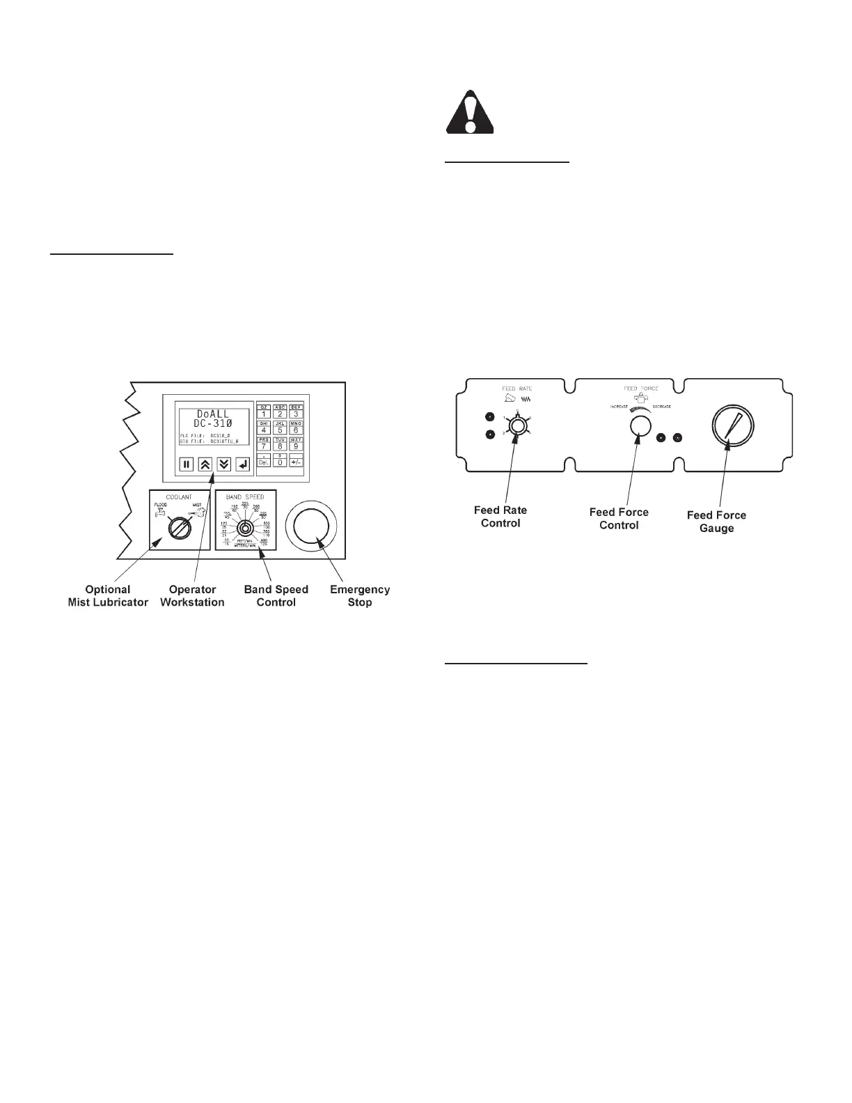
1. Machine controls are located on top of the electrical
box enclosure on the left front of the machine. These
controls include: (a) A hydraulic control panel with
a Feed Rate control and Feed Force control and
Gauge; (b) A control panel that includes a Emer-
gency Stop pushbutton; a Band Speed control and
an Operator Workstation to operate all other saw
functions.
Electrical Controls
1. Emergency Stop. Pushing this red mushroom
head button stops all machine motors (band drive,
hydraulic pump, coolant pump and optional chip
conveyor) simultaneously. This button must be
released or reset (rotate button head clockwise)
before the machine can be restarted.
Electrical Controls.
2. Band Speed. Band speed is innitely variable
between 50 and 400 fpm (15 and 120 m/min).
To adjust, turn the band speed knob clockwise
to "increase" band speed; counterclockwise to
"decrease" it.
3. Coolant (Optional). This selector switch allows
the operator to select between the standard "ood"
coolant or the optional "mist" lubricator system.
4. Operator Workstation. The workstation is program-
mable to allow data entry by means of a numeric
keypad. Also there is a display to show important
saw paramters and operation data.
• See "Operator Workstation" later in this section for
complete descriptions and operation of the worksta-
tion.
5. A Disconnect Switch is located on the control box
enclosure.
Turn the disconnect switch to OFF before
opening the electrical enclosure.
Hydraulic Controls
1. Feed Rate. This valve regulates the saw head’s
descending rate. Turn the knob counterclockwise
to “increase” the velocity; clockwise to “decrease”
it.
2. Feed Force. This valve regulates the amount of
pressure being placed by the saw band against the
workpiece. Turn the knob clockwise to “decrease”
pressure; counterclockwise to “increase” it. The
valve’s lower locking knob helps maintain the set-
ting.
Hydraulic Control Panel.
3. Feed Force Indicator. This gauge shows the
amount of pressure being placed by the saw band
against the workpiece.
Operator Workstation
1. The workstation consists of a numeric keypad for
entering data, a display for showing data and set
of four (4) function keys.
2. The function keys operate as follows:
• Data Enter. Pressing this key allows the operator
to enter data into the display.
• Previous Screen. This key allows the operator to
scroll "back" to the previous screen. Pressing the
key again will continue to scroll "back" until you
reach the "start-up" screen. It will not scroll "back"
any further.