21
2. In addition, the operator should check often for chip
accumulations around such machine areas as: saw
guides, vise bed, vise jaws, head feed cylinder, etc.
These accumulations may affect machine perfor-
mance if not removed. Using the ushing hose to
wash the chips from these areas. Remove chip
accumulations at least twice per eight (8) hour
shift and more often with heavier use.
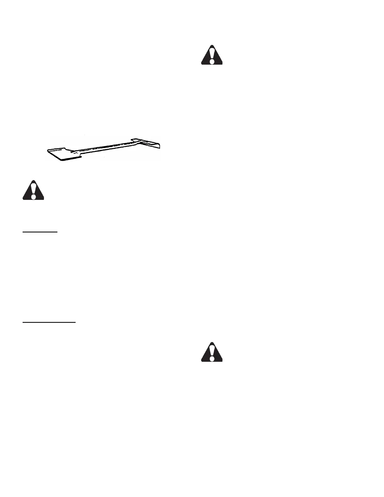
3. Use the supplied shovel-rake to remove accumu-
lated chips or other materials from the machine's
operating areas.
Combination Shovel-Rake.
Be sure the band drive motor and the saw band
are STOPPED completely before cleaning the
machine.
TYPICAL OPERATION PROCEDURES
Preparation
1. These operations assume that the machine is pre-
pared as follows: (a) The band drive motor is off; (b)
The saw band is properly installed and tensioned;
(c) Both bandwheel doors are closed; (d) All guards
are in place and/or secured; (e) The coolant res-
ervoir is full and all lubrication points are properly
serviced; (f) The band brush is properly positioned;
(g) Any inboard/outboard material handling equip-
ment if supplied are properly positioned.
Manual Operation
1. Scroll through the screens until the HYDRAULIC
PUMP control is displayed. Press the "1" key to
start the hydraulics.
2. Adjust the index and xed movable vise jaws to
accommodate the material.
3. Scroll through the screens until the SAW HEAD
control is displayed. Press the "1" key to raise the
saw head until the sensing arm is not contacting
the material. Press the "2" key to hold.
4. Load the stock into cutting position (either manually
or by using the index vise controls) and scroll to the
INDEX VISE control. Press the "3" key to clamp
the index vise jaw. The xed vise does not have to
be clamped if desired.
5. Turn the Feed Rate control fully clockwise to stop
the feed.
DO NOT over tighten. To prevent damage to
the Feed Force valve, turn only enough to seat
the needle of the valve.
6. Scroll to the SAW HEAD control. Press and release
the "3" key to allow the saw head to lower (saw
head will not lower at this time because the band
drive motor is not running).
7. Scroll to the CYCLE MODE control. Press the "1"
key for "manual" operation.
8. Press the "7" key to start the band drive motor.
Adjust the band speed to the recommended speed
from the Job Selector. Next: (a) Turn the Coolant
valve on the saw guide arm counterclockwise
until coolant completely covers both sides of the
saw band.
• The band drive motor will start and the saw head
will rapid descend until the head raise limit wand
strikes the material. Then the feed rate will switch
to the operator setting. The machine will start
the cut when the operator adjusts the Feed Rate
control to allow the saw head descend at optimum
efciency.
9. Adjust the band speed, feed force and coolant
ow as necessary during the cutting procedure.
The operator may interrupt the cycle by pushing
the "9" key or in the SAW HEAD control screen,
press the "2" key to "hold" (either way will stop both
saw head fall and the band drive motor). Push the
Emergency Stop button for immediate stoppage
of all machine functions.
10. When the cut has been completed, the saw head
will remain in the down position and the band drive
motor will shut off.
DO NOT remove the cut-off piece until the saw
band has stopped completely.
11. If more cuts are to be made: (a) In the SAW HEAD
control screen, press the "3" key to raise the saw
head to proceed upward until the head raise limit
sensing arm is off the material; (b) Press the "2"
key to hold the saw head; (c) Position stock for
another cut; (d) Scroll to the BAND DRIVE control
screen and press the "7" key to start the band drive
motor.
BAND BRUSH AND CHIP REMOVAL
(Continued....)