28
BAND TENSION MEASUREMENT
1. Tension adjustment of the saw band will be nec-
essary from time to time. Adjustment is made by
turning the band tension handwheel extending from
the saw head's left side.
2. Correct band tension will stress a high-speed steel
saw band to 26,250 psi (1845.6 kg/cm²). This is
comparable to a DoALL Tensigage reading of "3.5".
Refer also to the band tensioning portion of the
"Operation" section of this manual.
3. A DoALL Tensigage reading of 3.5 indicates correct
saw band tension.
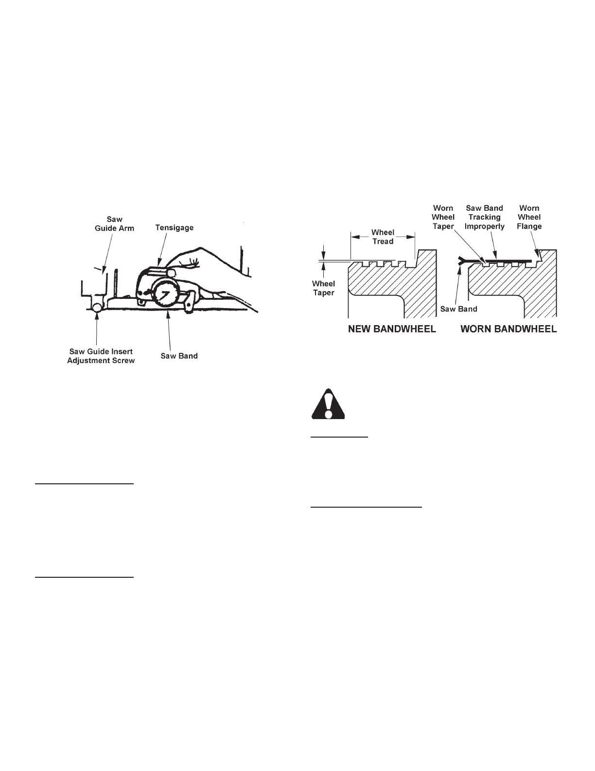
Using a Tensigage to Measure Band Tension.
WEAR PLATE REPLACEMENT
1. The wear plates must be replaced before excessive
wear causes the mounting screw heads to become
damaged and makes removal difcult.
Vise Jaw Wear Plates
1. The machine has a total of four (4) vise jaw wear
plates -- one (1) on each vise jaw. All wear plates
are mounted with low-head screws. Be sure the
vise jaws are separated and the machine turned
off when replacing the wear plates.
Vise Bed Wear Plates
1. All wear plates are mounted with low-head screws.
Replacement requires: (a) Disconnecting the
clamping cylinder from the movable vise jaw; (b)
Removing the movable vise jaw; (c) Removing the
mounting screws and then the wear plates.
2. After replacing the wear plates, reinstall the low-head
screws and the movable vise jaw and reconnect the
clamping cylinder.
BANDWHEELS
1. Occasionally check each bandwheel’s back-up
ange and wheel tread for wear. Saw bands will
not track properly if the taper is worn from the wheel
tread.
2. Replace the entire bandwheel if the rim becomes
badly worn.
3. Ideally, the saw band should be tracking on both
wheels so that the back edge will just lightly contact
the wheel anges, or is not more than 0.005 inch
(0.127 mm) away from the anges.
Bandwheel Flange and Tread.
CLEANING CHIP TROUGH/CHIP CONVEYOR
The band drive motor must not be running
when cleaning the trough or chip conveyor.
Chip Trough
1. Chips may be removed using the shovel rake or
sliding out the entire trough and dumping the chips
into an approved container.
Optional Chip Conveyor
1. Disconnect the hydraulic hoses. Then: (a) Pull the
conveyor from its cradled position in the base; (b)
Clean the conveyor trough; (c) Clean the reservoir
oor; (d) Replace the conveyor.