8
6. Install conveyor(s) or material handling equipment
if supplied as accessory equipment. These do not
attach to the machine and should be anchored
totheoorseparately.
ELECTRICAL INSTALLATION
Electrical installation must be made by autho-
rized electrical maintenance personnel only.
1. Refer to the machine data plate on the saw head
frame to verify that the electrical supply circuit will
meet the voltage/phase/frequency/amperage re-
quirements listed. A basic data plate is reproduced
on this manual’s introductory page.
2. The electrical supply to this machine must be a
dedicated circuit.
3. Set the disconnect switch on the electrical cabinet to
OFF. Then: (a) Loosen the screws at the left door
edge of the electrical cabinet and open the door;
(b) Familiarize yourself with the operation of the
disconnect switch operating handle, door interlock
function, switch drive dog and shaft/clamp operating
postions; (c) Familiarize yourself with the location
of internal components such as circuit breakers,
fuses, transformer, contacts, etc.
4. The following are important disconnect precau-
tions:
The disconnect must be ON before the machine
will operate.
The enclosure must be closed and the ap-
propriate securing screws must be in place
before starting machine operation.
5. Punch a one (1) inch (25.4 mm) diameter or larger
hole in the side of the electrical cabinet. Then: (a)
Bring power wiring (L1, L2, L3 and ground) through
the hole (the cable and connector are to be supplied
by the customer). DO NOT bring the power cable
through any holes in the back wall. These are
for installation of future accessories.
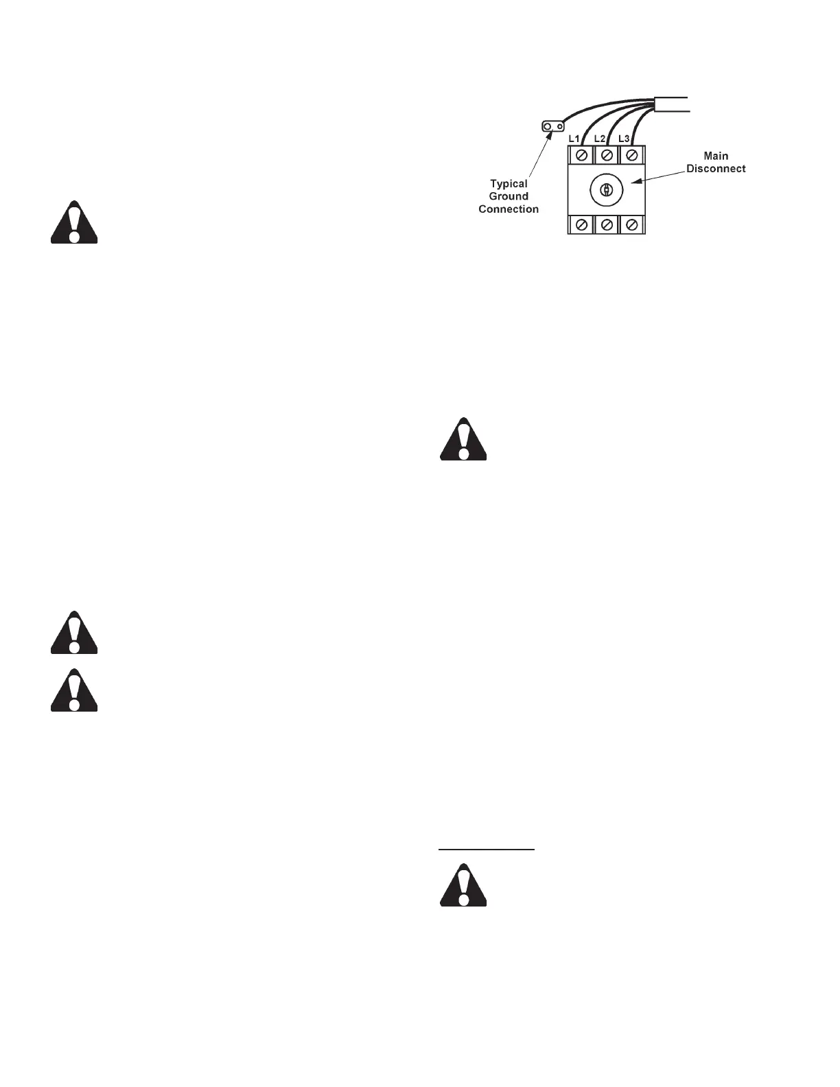
6. Bring the power cable leads up to the disconnect
switch. Then: (a) Connect L1, L2 and L3 to their
respective terminals; (b) Connect the ground wire to
the ground terminal (refer to the electrical schematic
if necessary).
Electrical Connections to Disconnect Switch.
7. Place the operating shaft and operating handle of
the disconnect switch in the OFF position. Then:
(a) Close the electrical cabinet door and secure its
screws; (b) Now turn on the electrical supply and
disconnect switch (no action will occur until the
HYDRAULIC PUMP control on the workstation has
been started).
DO NOT start machine hydraulics until the
following “Preparation for Use” procedures
have been performed.
PREPARATION FOR USE
1. Check the hydraulic reservoir uid level. Capacity
is 10 gallons (37.8 liters). If the reservoir level is
low (or empty): (a) Check to see that the reservoir’s
drain plug (located on the bottom of the tank) is in-
stalled tightly; (b) Replace the plastic shipping plug
with the ller/breather cap (in box of extra parts);
(c) If necessary, ll to the top of the sight gage with
multi-purpose automatic transmission uid.
2. The coolant reservoir capacity is 15 gallons (56.8
liters). Fill with uid recommended by the Lubrica-
tion Chart (pour coolant slowly into the chip trough).
DO NOT let coolant spill out of the openings in
thebaseandontotheoor.
3. Check to see that all other points listed by the Lu-
brication Chart have been properly checked and/or
serviced.
Motor Start-Up
Read this section and proceed to "Hydraulic
Start-Up" before turning motors on.
1. All motors were installed and operated at the factory
during assembly. If the rst motor to be checked
(hydraulic power unit motor) rotates correctly, the
band drive motor will do likewise.
FLOOR INSTALLATION (Continued....)