27
2. Pressure is adjusted by turning the screw extending
outward from the hydraulic pump. Consult a DoALL
Industrial Supply Center service representative if
assistance is needed.
Pump Repair & Replacement
1. DO NOT attempt to repair the hydraulic pump.
Return it to the factory for repair or replacement. Be
sure to specify the correct pump model and serial
numbers when returning the unit.
2. Following a new pump installation, scroll to the rst
screen which has the HYDRAULIC PUMP control.
Then: (a) Jog the "1" (Start) and "3" (Stop) keys
several times — on for two (2) seconds, off for three
(3) seconds — until the pump is primed; (b) Check
for proper pump rotation while jogging; (c) Review
wiring connections if the pump rotates in the wrong
direction.
After the pump has been primed, run it
for several minutes while operating the
machine’s controls to purge entrapped air
from the pump and system. Check for oil
leaks while the system is being operated.
Seals & Cups
1. Seals and cups used in DoALL hydraulic systems
are compatible ONLY with hydraulic oils having an
aniline point between 215° and 230° F. (102° and
111° C.).
2. If hydraulic oil having an aniline point not falling
within the above range is used, the seals may either
swell or shrink and harden. This causes machine
malfunction and leakage.
DOALLhydraulicuid--withananilinepoint
ofapproximately221°F.(106°C.)--willnot
cause deterioration of component seals.
COOLANT SYSTEM
1. The machine’s coolant reservoir has a 19 gallon
(71.9 liter) capacity.
2. Check the coolant often for signs of contamination
or breakdown. The reservoir and coolant system
should be drained and cleaned thoroughly when the
cutting uid becomes undesireable for further use.
If another type of coolant is to be used, the entire
coolant system must be ushed (use DoALL’s Kleen
Flush).
3. To thoroughly clean the reservoir section below
the conveyor trough, removal of the trough will be
necessary.
MACHINE CLEANING
1. Keep the machine and its parts as clean as possible
to prevent excessive wear and damage.
2. Use the ushing hose as soon as possible to remove
metal chips and other waste materials which may
collect around the saw guides, bandwheels, vises,
slides, sensing arm, etc. The hose has a hand-
operated valve and attaches to the coolant pump.
The DoALL Company recommends using the
ushinghosetoremovechipsatleasttwiceper
each eight (8) hour shift, and more often with
heavier use.
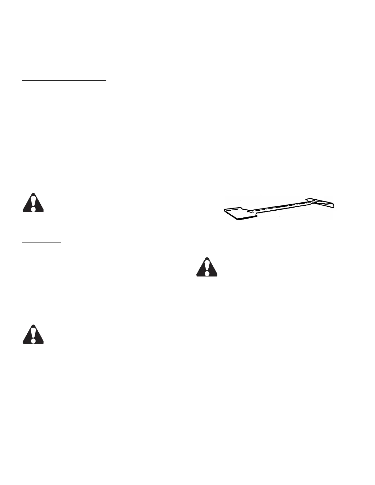
3. Use the supplied shovel-rake to remove accumulated
metal chips or other waste materials from machine
areas. Be sure the band drive motor is stopped
before opening machine doors or covers.
Combination Shovel-Rake.
MACHINE ALIGNMENT
DO NOT attempt any alignment procedures
not covered by this manual. Contact a DoALL
Industrial Supply Center service representa-
tive in such cases because special xtures
and techniques may be required.
BAND BRUSH
1. The band chip brush should be positioned so that its
bristles remove all metal chips from the blade tooth
gullets, but do not touch the bottom of the gullets.
Replace the brush if its bristles become too worn
for proper blade cleaning. DoALL replacement
band brushes are recommended.
2. To replace the brush or adjust it to a new position:
(a) Loosen the bracket screws; (b) Replace the
brush or move it toward the saw band; (c) Tighten
the bracket.
HYDRAULIC SYSTEM (Continued....)