19
HEAD RAISE LIMIT SENSING ARM
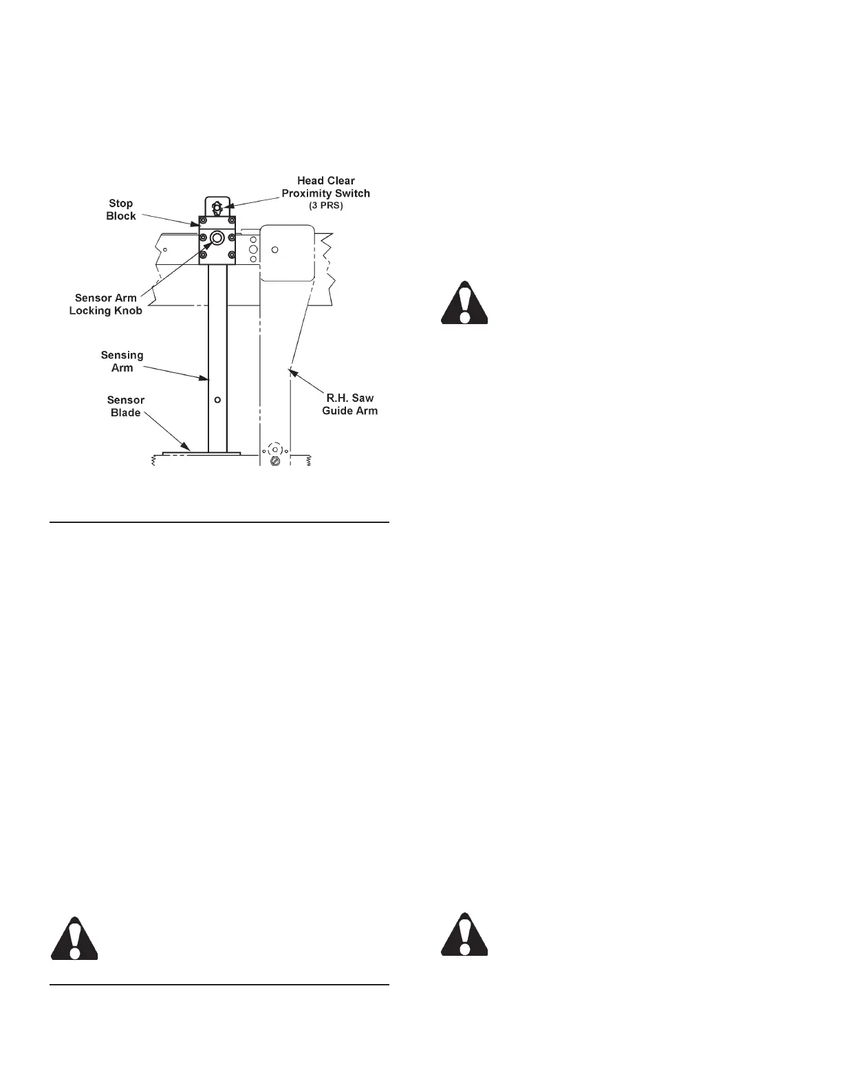
1. The sensing arm works in conjunction with the
head clear proximity switch (3 PRS) to assure that
the saw head has raised sufciently above existing
stock so that automatic indexing (or manual stock
positioning) can be accomplished safely.
Head Raise Limit Sensing Arm.
Sensing Arm Operation When the Saw Head Raises
1. The saw head lifts the sensing arm above the stock
at a rapid rate (there is no slow head raising rate)
until it actuates the head clear proximity switch (3
PRS). This causes saw head upward movement
to stop when the blade is approximately one (1)
inch (25.4 mm) above the stock. This clearance
anticipates potentially crooked and/or out-of-round
stock being used.
2. If operating in automatic mode, the xed vise then
unclamps, and stock is indexed forward. Following
the advance of stock, the xed vise clamps and the
index vise unclamps.
3. When the xed vise unclamps prior to indexing, its
jaws open just enough to allow stock advancement.
The vise jaws can be opened wider only when the
saw head has been manually raised to the full "up"
position to actuate the head up proximity switch (2
PRS). This assures that the left saw guide arm will
clear the xed vise when it opens to receive larger
stock.
Left saw guide arm adjustment for stock width
must be made manually by the operator.
Sensing Arm Operation When the Saw Head Lowers
1. The saw head lowers until stock is contacted by the
sensing arm.
2. Sensing arm contact with the stock is maintained
throughout the cut. After a cut has been nished:
(a) The head down proximity switch (5 PRS) is
actuated; (b) The saw head raises.
VISE JAW ADJUSTMENT
1. The distance between the xed (right) and movable
(left) vise jaws can be adjusted to accommodate
varying stock widths. To adjust, scroll through the
screens until the INDEX VISE and FIXED VISE
controls are displayed. Then press the desired key
to open or clamp the vise jaws.
The hydraulics MUST be "on", the operation
mode MUST be in "manual" for the vise con-
trols to operate.
2. For index lengths between .50 and 1.75 inches
(12.7 and 44.4 mm), replace standard serrated wear
plate on the movable jaw of the outboard vise with
a recessed wear plate (box of extra parts).
MATERIAL INDEXING
1. Your machine is capable of a 16 inch (406.4 mm)
single stroke index (minimum is 0.50 inch (12.7
mm). It can also is capable of a 10X multiple index
up to a maximum length of 160 inches (4064.0
mm).
2. A movable roller assembly to help support the mate-
rial is located behind the index vise. It is connected
to the index vise by a rod that allows the roller to
move with the movement of the index vise.
3. Index length is set in the JOB ENTRY screen which
is on the rst screen . Press the "6" key on the
numeric keypad to access this screen.
• To enter data, press the Data Entry function key.
Then: (a) With the length eld highlighted, enter
the length of the cut using the numeric keypad; (b)
Press the Accept function key to enter the data
into memory; (c) With the quanitity eld highlighted,
enter the number of cuts using the numeric keypad;
(d) Press the Accept function key to enter the data
into memory;(e) With the next job's eld highlighted,
continue as above; (d) When there is no highlighted
eld, press the NextScreen key to move to the next
set of two (2) jobs to be programmed.
If you make an error in entering data, just press
the Data Enter key again, change your entry
and then press the Accept key.