17
Saw Band Removal
Alwaysuseextremecarewhenhandlingsaw
bands. Wear gloves.
1. Scroll through the screens until the BAND/CYCLE
control is displayed. Then: (a) Press the "9" key
on the numeric keypad to stop the band drive motor
(only the hydraulics should be running); (b) Turn the
band tension handwheel counterclockwise (this
moves the idler bandwheel to the left and releases
band tension).
2. Scroll through the screens until the SAW HEAD
control is displayed. Then: (a) Press the "1" key
on the numeric keypad to raise the saw head to the
maximum up position; (b) Press the "2" key to stop
saw head movement.
3. Open both bandwheel doors. Then: (a) Remove
or reposition the band brush, if necessary; (b) If
desirable, remove the right and left blade guards; (c)
Loosen the saw guide inserts by turning counter-
clockwise; (d) Loosen the saw guide arm locking
handwheel and slide the saw guide arm as close
to the other saw guide arm as possible.
4. Place your gloved hand on the non-cutting edge of
the saw band between the saw guide arms. Then:
(a) Push the saw band downward to free it from the
saw guide inserts; (b) Grasp the saw band near the
idler bandwheel and remove it, then remove the saw
band from around the drive bandwheel; (c) Move
the saw band's upper strand down and under both
saw guide arms; (d) Slip the saw band out from the
upper saw band guard.
Immediately dispose of the old or broken saw
band. If possible, recoil the saw band into the
original holder before scrapping it.
Saw Band Installation
Alwaysuseextremecarewhenhandlingsaw
bands. Wear gloves.
1. Remove the old or broken saw band as described in
the previous section. Clean metal chips and other
foreign materials and debris from around the saw
guides and both bandwheels.
2. Form the saw band into a loop. Then: (a) With the
saw band's teeth facing towards you, slip the looped
saw band behind the outboard vise jaws and then
around the drive and idler bandwheels; (b) Slide
the saw band through the opening in the upper saw
band guard; (c) Maneuver the saw band under the
saw guide arms and into approximate position for
placement.
3. Twist the saw band 90° so that its teeth between
the saw guide arms point down and towards the
xed jaw. Then: (a) Insert the saw band into the
saw guide inserts and pull up against the back-up
bearing; (b) Check the saw band's position around
the bandwheels (its back edge must rest against
each bandwheel's rear ange).
4. Apply correct band tension (see below) by turning
the band tension handwheel clockwise. Then:
(a) Remove the new saw band's protective cap;
(b) Turn the saw guide insert adjustment screws
clockwise until tight (do not over tighten); (c) Turn
each adjustment screws back counterclockwise
1/4 to 1/2 turn; (d) Reposition or mount the band
brush and if necessary, the saw band guards; (e)
Close both bandwheel doors.
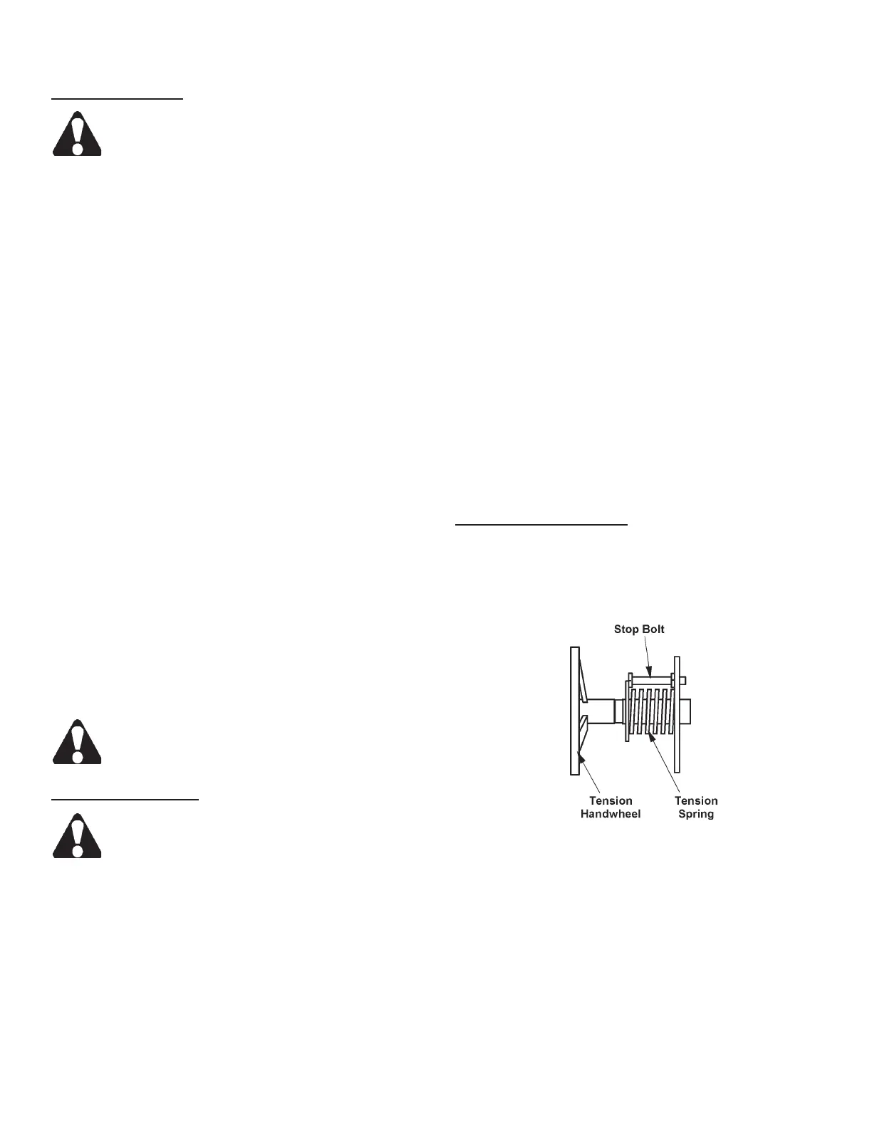
Band Tension Handwheel
1. Band tension is applied by turning the handwheel
which protrudes from the saw head's left side.
Turn the handwheel clockwise to increase band
tension;counterclockwise to decrease it.
Turn Handwheel to Set Band Tension.
2. Correct band tension for the machine's standard
1.25 inch (31.7 mm) wide by 0.042-inch (1.07 mm)
gage saw band is 3.5 units measured by a DoALL
Tensigage. This tension setting is established when
the preset stop bolt contacts the large washer.
An escutcheon near the band tension handwheel
describes the washer to stop bolt relationship in a
setting of 26,250 psi (1845.6 kg/cm²).
SAW BAND PREPARATION (Continued....)