INSTALLATION
A-12 20509 Issue 7 Jan 2018
PRODUCT DETECTOR INSTALLATION
A product detector is mounted where it can sense products as they
approach the printer (see
page 2-20).
Macrojet 2 can be fitted with one or two sensors. Allocation of print heads
to sensors is part of the data input to the printer, - see Pocket Terminal
User's Guide.
For basic coding, the product sensor should be positioned as close as
possible to the print head. Macrojet 2 is supplied with two clips which can
be fitted to the print head. They are attached to the "upstream" side using
the two screws already fitted into the print head cover.
The final print position is adjusted using the Print Go delay (part of the print
message input data) - see Pocket Terminal User's Guide.
Setting up the Print Go signal in the printer is automatic. Further
information is given in Part 3: Universal Serial Interface PCB.
Reflective
This detector is supplied as part of a Photocell Detector and Reflector kit.
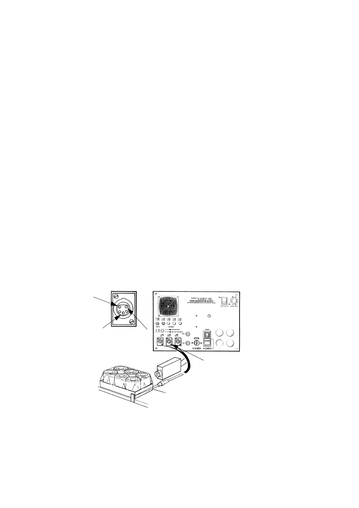
Connection details are given in the diagram below.
The detector and reflector are fitted on opposite sides of the product line.
The reflector is adjusted so that a light beam from the detector, directed
across the line, is reflected back into a photocell in the detector. Products
moving in between the detector and reflector break the light beam and this
is used to start the printing process, either as the beam is broken or as it is
restored. The basic requirement is, therefore, gaps between product items
as they pass the detector.
Pin 5 =
+12V
Pin 3 =
Print Go
Pin 1 = 0V
Product Detect
Inputs 1 & 2
Reflective Detector
TP7160_1
 Loading...


