INSTALLATION
20509 Issue 7 Jan 2018 A-15
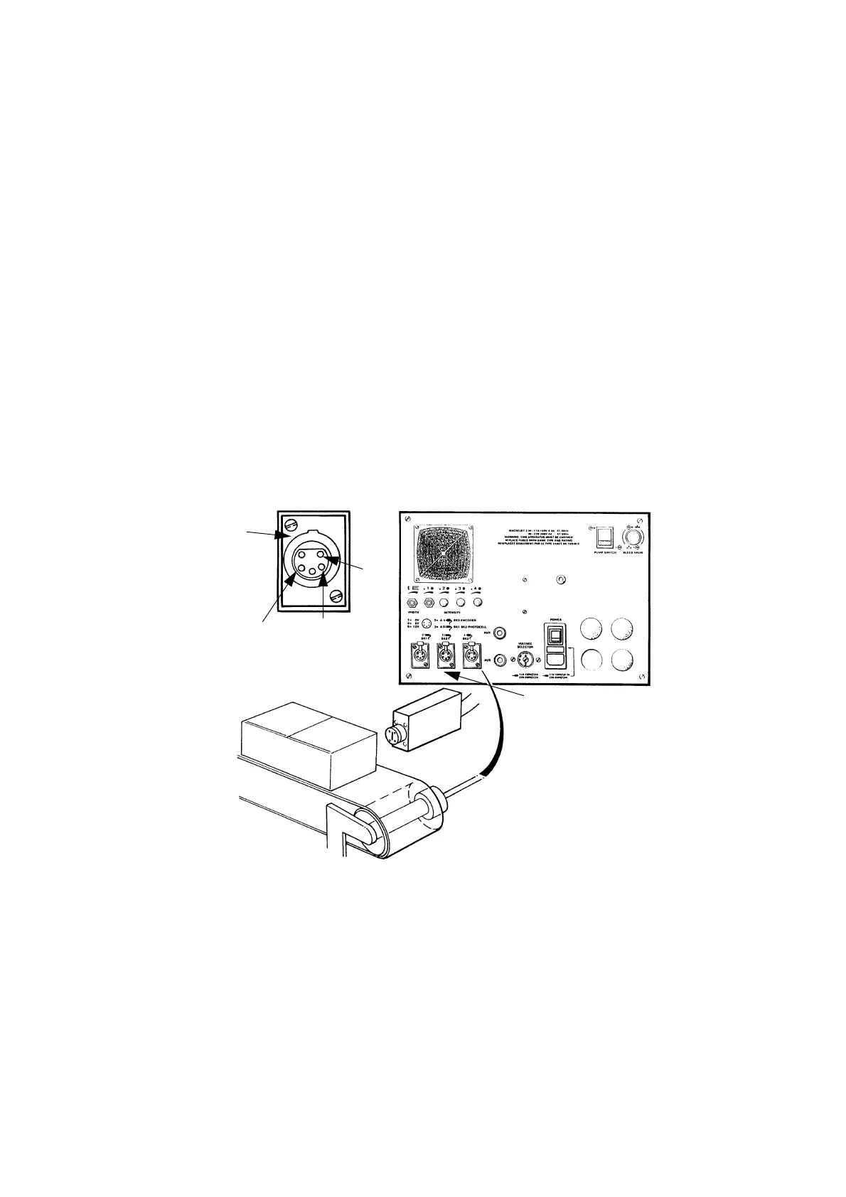
SHAFT ENCODER (OPTIONAL)
The shaft encoder is fitted to the production line so that its rotation follows
the line speed. Fitting details depend upon the line.
Connection into the printer is to the SHAFT ENCODER connector on the
rear panel of the cabinet. The printer provides a +5V or +12V dc supply for
use by the shaft encoder and a +12V NPN open-collector input for signals
from the encoder.
For internal printer adjustments, refer to the link selections in Part 3:
Replacing the Universal Serial Interface PCB.
Domino will provide advice on an appropriate encoder. As well as electrical
factors, selection is based on the print width required and the line speed.
The following calculation illustrates how these are used in defining the
encoder.
Each printed character is made up of a fixed number of strokes. This
number must be determined from the type of printer and the message.
Examples are as given on the following page:
Pin 5 =
+12V
Pin 4 =
+5V
Pin 1
= 0V
Product Detect
Inputs 1 & 2
Shaft Encoder Installation
TP7163_1
Pin 2 = Encoder
Signal
 Loading...


